Data Field Defaults
This topic contains a listing of default flag operations.
The table contains the following columns:
|
Object Type |
The network object type. |
|
Field Name |
The display name for the field. This is the name at the head of a column in the grid or beside an edit box or dropdown list on the property sheet. |
|
Page Name |
Property Sheet Page on which field can be viewed. |
|
Default |
Value, method of calculation or source of value. |
|
Object Type |
Field Name |
Page Name |
Default |
|---|---|---|---|
| CCTV Survey | Surveyed Length | Summary | Distance of final defect entry on Defects Page |
| Borehole | X and Y Coordinates | Definition | Set the default flag for the X and Y coordinate of a lateral node to move the node if the associated lateral pipe is moved. The node will be moved so that it remains on the pipe. The specified Lateral Distance from Start node will be maintained. |
| Connection Node | X and Y Coordinates | Definition | Set the default flag for the X and Y coordinate of a lateral node to move the node if the associated lateral pipe is moved. The node will be moved so that it remains on the pipe. The specified Lateral Distance from Start node will be maintained. |
| Drain Test | X Coordinate | Definition | X coordinate of associated property |
| Drain Test | Y Coordinate | Definition | Y coordinate of associated property |
| Fitting | X and Y Coordinates | Definition | Set the default flag for the X and Y coordinate of a lateral node to move the node if the associated lateral pipe is moved. The node will be moved so that it remains on the pipe. The specified Lateral Distance from Start node will be maintained. |
| Flume | X Coordinate | Definition | X Coordinate of centre of Ancillary as drawn on the GeoPlan. (The location of the ancillary on the GeoPlan will not be changed if the X Coordinate is edited.) |
| Flume | Y Coordinate | Definition | Y Coordinate of centre of Ancillary as drawn on the GeoPlan. (The location of the ancillary on the GeoPlan will not be changed if the Y Coordinate is edited.) |
| Flume | Length | Details | Calculated from node coordinates and link geometry |
| GeoExplorer Zone | Zone Area | Zone Definition | Calculated from zone geometry |
| GPS Survey | X Coordinate | Definition | X coordinate of associated asset |
| GPS Survey | Y Coordinate | Definition | Y coordinate of associated asset |
| Hydrant | X and Y Coordinates | Definition | Set the default flag for the X and Y coordinate of a lateral node to move the node if the associated lateral pipe is moved. The node will be moved so that it remains on the pipe. The specified Lateral Distance from Start node will be maintained. |
| Hydrant Maintenance | X Coordinate | Definition | X Coordinate of associated Hydrant |
| Hydrant Maintenance | Y Coordinate | Definition | Y Coordinate of associated Hydrant |
| Hydrant Test | Water Used | Definition | Sum of Water Used values on Flow Hydrants Page |
| Hydrant Test | X Coordinate | Definition | X Coordinate of associated Hydrant |
| Hydrant Test | Y Coordinate | Definition | Y Coordinate of associated Hydrant |
| Hydrant Test | Flow | Graph | Sum of Flow values on Flow Hydrants Page |
| Hydrant Test | Calculated Flow | Graph |
Calculated from other values on Graph Page: 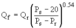
Where: Qf = fire flow at 20 psi (gpm) Qr = residual Flow at pitot pressure (gpm) Ps = Static Pressure (psi) Pr = Residual Pressure (psi) |
| Incident | X Coordinate | Definition | X Coordinate of associated Node, Pipe or Property |
| Incident | Y Coordinate | Definition | Y Coordinate of associated Node, Pipe or Property |
| Leak Detection | X Coordinate | Definition |
The order of precedence of calculating coordinates is as follows:
|
| Leak Detection | Y Coordinate | Definition |
the order of precedence of calculating coordinates is as follows:
|
| Manhole Repair | X Coordinate | Definition | X Coordinate of associated Node/Manhole |
| Manhole Repair | Y Coordinate | Definition | Y Coordinate of associated Node/Manhole |
| Manhole Survey | X Coordinate | Node | X Coordinate of associated Node/Manhole |
| Manhole Survey | Y Coordinate | Node | Y Coordinate of associated Node/Manhole |
| Meter | X and Y Coordinates | Definition | Set the default flag for the X and Y coordinate of a lateral node to move the node if the associated lateral pipe is moved. The node will be moved so that it remains on the pipe. The specified Lateral Distance from Start node will be maintained. |
| Meter Maintenance | X Coordinate | Definition | X Coordinate of associated meter |
| Meter Maintenance | Y Coordinate | Definition | Y Coordinate of associated meter |
| Meter Test | X Coordinate | Definition | X Coordinate of associated meter |
| Meter Test | Y Coordinate | Definition | Y Coordinate of associated meter |
| Monitoring Survey | Sensor Level | Details | Reference Level - Sensor Depth Below Reference |
| Monitoring Survey | X Coordinate | Definition | X Coordinate of Monitored Node |
| Monitoring Survey | Y Coordinate | Definition | Y Coordinate of Monitored Node |
| Node | X and Y Coordinates | Definition | Set the default flag for the X and Y coordinate of a lateral node to move the node if the associated lateral pipe is moved. The node will be moved so that it remains on the pipe. The specified Lateral Distance from Start node will be maintained. |
| Node | Chamber floor depth from cover | Construction | From greatest Depth from Cover value of connected pipes |
| Orifice | X Coordinate | Definition | X Coordinate of centre of Ancillary as drawn on the GeoPlan. (The location of the ancillary on the GeoPlan will not be changed if the X Coordinate is edited.) |
| Orifice | Y Coordinate | Definition | Y Coordinate of centre of Ancillary as drawn on the GeoPlan. (The location of the ancillary on the GeoPlan will not be changed if the Y Coordinate is edited.) |
| Pipe (Collection) | US InvertLevel | Construction | Cover Level of US Node - US Depth from Cover |
| Pipe (Collection) | Pipe Length | Construction | Calculated from upstream and downstream node coordinates and link geometry |
| Pipe (Collection) | Gradient | Construction | Calculated from pipe length and US and DS Invert levels |
| Pipe (Collection) | DS Invert Level | Construction | Cover Level of DS Node - DS Depth from Cover |
| Pipe (Collection) | DS Shape ID | Dimensions | US Shape ID |
| Pipe (Collection) | DS Height | Dimensions | US Height |
| Pipe (Collection) | DS Width | Dimensions | US Width |
| Pipe (Collection) | DS Pipe Material | Construction | US Pipe Material |
| Pipe (Collection) | DS Lining Type | Construction | US Lining Type |
| Pipe (Collection) | DS Lining Material | Construction | US Lining Material |
| Pipe (Collection) | US Shape ID | Dimensions | DS Shape ID |
| Pipe (Collection) | US Height | Dimensions | DS Height |
| Pipe (Collection) | US Width | Dimensions | DS Width |
| Pipe (Collection) | US Pipe Material | Construction | DS Pipe Material |
| Pipe (Collection) | US Lining Type | Construction | DS Lining Type |
| Pipe (Collection) | US Lining Material | Construction | DS Lining Material |
| Pipe (Distribution) | Pipe Length | Details | Calculated from start and end node coordinates and link geometry |
| Pipe Clean | Node ID Flushing From | Definition | Determined from the details provided on the Pipes page of the property sheet |
| Pipe Clean | Node ID Flushing to | Definition | Determined from the details provided on the Pipes page of the property sheet |
| Pipe Repair | Start Length | Definition | 0.000 (representing location of start of associated pipe) |
| Pipe Repair | Repair Length | Definition | Calculated from: Length of associated Pipe - Start Length of Pipe Repair |
| Pipe Sample | Start Length | Definition | 0.000 (representing location of start of associated pipe) |
| Pipe Sample | Sample Length | Definition | Calculated from: Length of associated Pipe - Start Length of Pipe Sample |
| Property | X Coordinate | Definition | Collection Networks Property created as Polygon: X Coordinate of centre of Property as drawn on the GeoPlan. |
| Property | Y Coordinate | Definition | Collection Networks Property created as Polygon: Y Coordinate of centre of Property as drawn on the GeoPlan. |
| Pump | X Coordinate | Definition | Collection Networks: X Coordinate of centre of Ancillary as drawn on the GeoPlan. (The location of the ancillary on the GeoPlan will not be changed if the X Coordinate is edited.) |
| Pump | Y Coordinate | Definition | Collection Networks: Y Coordinate of centre of Ancillary as drawn on the GeoPlan. (The location of the ancillary on the GeoPlan will not be changed if the Y Coordinate is edited.) |
| Pump Station | X Coordinate | Definition | Pump Station created as a Polygon: X Coordinate of the bounding rectangle of the Pump Station polygon. |
| Pump Station | Y Coordinate | Definition | Pump Station created as a Polygon: Y Coordinate of the bounding rectangle of the Pump Station polygon. |
| Screen | X Coordinate | Definition | X Coordinate of centre of Ancillary as drawn on the GeoPlan. (The location of the ancillary on the GeoPlan will not be changed if the X Coordinate is edited.) |
| Screen | Y Coordinate | Definition | Y Coordinate of centre of Ancillary as drawn on the GeoPlan. (The location of the ancillary on the GeoPlan will not be changed if the Y Coordinate is edited.) |
| Siphon | X Coordinate | Definition | X Coordinate of centre of Ancillary as drawn on the GeoPlan. (The location of the ancillary on the GeoPlan will not be changed if the X Coordinate is edited.) |
| Siphon | Y Coordinate | Definition | Y Coordinate of centre of Ancillary as drawn on the GeoPlan. (The location of the ancillary on the GeoPlan will not be changed if the Y Coordinate is edited.) |
| Sluice | X Coordinate | Definition | X Coordinate of centre of Ancillary as drawn on the GeoPlan. (The location of the ancillary on the GeoPlan will not be changed if the X Coordinate is edited.) |
| Sluice | Y Coordinate | Definition | Y Coordinate of centre of Ancillary as drawn on the GeoPlan. (The location of the ancillary on the GeoPlan will not be changed if the Y Coordinate is edited.) |
| Smoke Defect | X and Y Coordinates | Position | Calculated from Smoke Defect Direction, Distance Along Pipe, and Distance Across Pipe Values. Where: Distance Along Pipe is the distance from upstream/downstream node (as defined in Direction field) along a straight line between connected nodes of surveyed pipe. Distance Across Pipe is the distance perpendicular to the surveyed pipe. |
| Smoke Test | Defects Found check box | Definition | Box will be checked if there are any Smoke Defect Observation objects associated with the Smoke Test |
| Tank | X and Y Coordinates | Definition | Set the default flag for the X and Y coordinate of a lateral node to move the node if the associated lateral pipe is moved. The node will be moved so that it remains on the pipe. The specified Lateral Distance from Start node will be maintained. |
| Treatment Works | X Coordinate | Definition | X Coordinate of the bounding rectangle of the Treatment Works polygon. |
| Treatment Works | Y Coordinate | Definition | Y Coordinate of the bounding rectangle of the Treatment Works polygon. |
| User Ancillary | X Coordinate | Definition | X Coordinate of centre of Ancillary as drawn on the GeoPlan. (The location of the ancillary on the GeoPlan will not be changed if the X Coordinate is edited.) |
| User Ancillary | Y Coordinate | Definition | Y Coordinate of centre of Ancillary as drawn on the GeoPlan. (The location of the ancillary on the GeoPlan will not be changed if the Y Coordinate is edited.) |
| Valve | X Coordinate | Definition | Collection Networks: X Coordinate of centre of Ancillary as drawn on the GeoPlan. (The location of the ancillary on the GeoPlan will not be changed if the X Coordinate is edited.) |
| Valve | Y Coordinate | Definition | Collection Networks: Y Coordinate of centre of Ancillary as drawn on the GeoPlan. (The location of the ancillary on the GeoPlan will not be changed if the Y Coordinate is edited.) |
| Valve Maintenance | X Coordinate | Definition | X Coordinate of associated valve |
| Valve Maintenance | Y Coordinate | Definition | Y Coordinate of associated valve |
| Vortex | X Coordinate | Definition | X Coordinate of centre of Ancillary as drawn on the GeoPlan. (The location of the ancillary on the GeoPlan will not be changed if the X Coordinate is edited.) |
| Vortex | Y Coordinate | Definition | Y Coordinate of centre of Ancillary as drawn on the GeoPlan. (The location of the ancillary on the GeoPlan will not be changed if the Y Coordinate is edited.) |
| Weir | X Coordinate | Definition | X Coordinate of centre of Ancillary as drawn on the GeoPlan. (The location of the ancillary on the GeoPlan will not be changed if the X Coordinate is edited.) |
| Weir | Y Coordinate | Definition | Y Coordinate of centre of Ancillary as drawn on the GeoPlan. (The location of the ancillary on the GeoPlan will not be changed if the Y Coordinate is edited.) |
| Weir | Length | Details | Calculated from node coordinates and link geometry |
| Zone | Area | Zone | Calculated from polygon geometry |
| User Defined Object |
X and Y Coordinates Length Area |
n/a (User Defined Object properties are displayed on the Object Properties Window). |
X and Y coordinates (applies to user-defined objects that are points) X and Y coordinate of associated asset (applies to user-defined surveys) Length calculated from link geometry (applies to user-defined objects that are polylines) Area calculated from polygon geometry (applies to user-defined objects that are polygons). |