RTC Logic Example
Logic operators can be used to combine the results from two ranges to give a TRUE or FALSE result.
The following example shows the RTC for controlling the status of a pump depending on the depth in the controlling node and the flow in a downstream conduit.
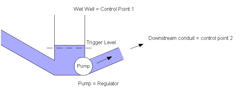
Under this example, the pump will be switched ON when the level at node K reaches 20mAD, providing the flow in conduit K.2 does not exceed 0.5 m3/s. At other times, the pump will be switched OFF by default.
The RTC is defined by adding components to a pump regulator in the RTC Window Editor.
Component | Parameters | Effect |
|---|---|---|
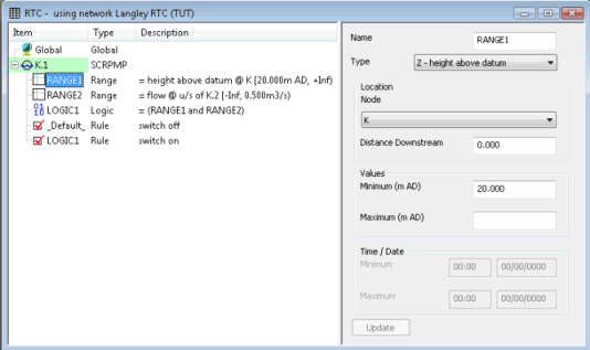
RANGE 1 | Range type: Z - height above datum | TRUE if water level at node K is greater than or equal to 20 mAD |
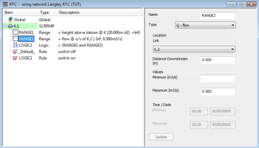
RANGE 2 | Range type: Q - flow | TRUE if flow in conduit K.2 is less than 0.5 m3/s |
LOGIC 1 | Operator: AND | TRUE if both RANGE 1 and RANGE 2 are TRUE |
RULE 1
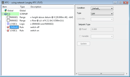
| Condition: _default_ | Default status of pump is OFF |
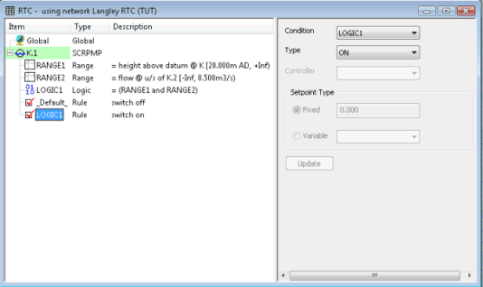
RULE 2 | Condition: LOGIC 1 | Switch on pump if LOGIC 1 is TRUE |
- Range 1: Defines node
K as a control point with a minimum value of 20 mAD
- Range 2: Defines Link
K.2 as a control link with a maximum value of 0.5 m3/s
- Logic 1: If the level
at node K is at or above 20 mAD and the flow in link K.2 is less than
0.5 m3/s, this logic statement is TRUE
- Rule 1: Unless subsequent
rules are true, the pump will be set to the default status of OFF
- Rule 2: Switches the pump
ON if the level at node K is at or above 20 mAD and the flow in link K.2
is less than 0.5 m3/s
For a further example of an RTC Scenario, see RTC Example.
