RTC Variable Example
A variable allows the combination of values (from a Range, Table, Logic operator, Variable or constant value) to derive another value.
All variables are set to zero at the beginning of a simulation. Variable values are preserved from timestep to timestep, so they can be used to accumulate statistics. A variable can also be used as a Timer.
Two examples of the use of variables are given below:
Variable Example 1 - Use of a Variable as a Timer
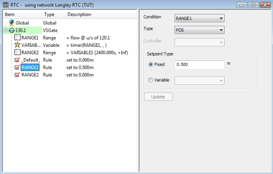
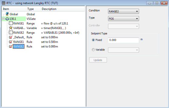
The following example models controlling the status of a sluice gate, by applying a time delay in order to close the sluice gate 40 minutes after it has been opened.
In this example, a variable is used as a timer. The timer starts when the sluice gate is opened. Once the timer has reached 40 minutes, the gate is closed.
The example is defined by adding components to a sluice gate regulator in the RTC Window Editor.
|
Component |
Parameters |
Effect |
|---|---|---|
|
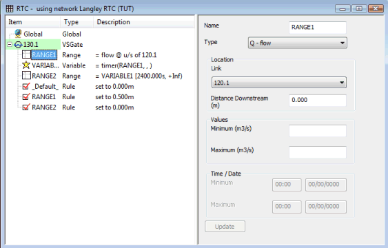
RANGE 1 |
Range type: Q - flow Location link: 120.1 Distance Downstream: 0m Minimum: Maximum: |
TRUE if flow in conduit 120.1 is between +/- infinity |
|
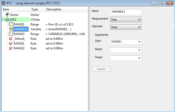
VARIABLE 1 |
Measurement: Time Operator: Timer Start: RANGE 1 |
Start Timer when RANGE 1 becomes TRUE |
|
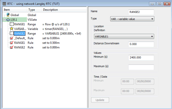
RANGE 2 |
Range type: Variable Location definition: VARIABLE 1 Minimum: 2400 s Maximum: |
TRUE if VARIABLE 1 is greater than 2400s |
|
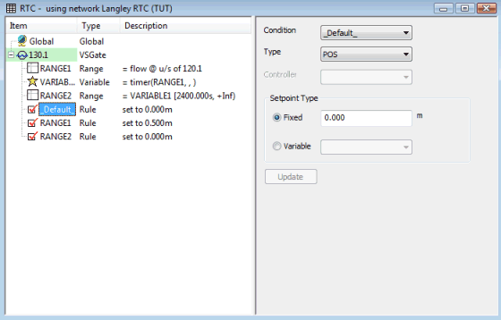
RULE 1 |
Condition: _default_ Rule type: POS Setpoint Type: FIXED 0.000 m |
DEFAULT status of gate is Closed |
|
RULE 2 |
Condition: RANGE 1 Rule type: POS Setpoint Type: FIXED 0.500 m |
Set sluice gate to 0.5 m if RANGE 1 is TRUE |
|
RULE 3 |
Condition: RANGE 2 Setpoint type: FIXED 0.000 m |
Set sluice gate to 0.0 m if RANGE 2 is TRUE
|
- Range 1: Defines Link
120.1 as a control link
- Variable 1: Starts Timer
when flow in link 120.1 is greater than or equal to 0.01 m3/s
- Range 2: Defines the calculated
time in Variable 1 as a control with a minimum value of 2400s (40 mins)
- Rule 1: Unless subsequent
rules are TRUE, sluice gate is closed
- Rule 2: Unless subsequent
rules are TRUE, sets sluice gate opening to 0.5 m
- Rule 3: When the Timer
defined in Variable 1 reaches 2400s (40 mins), sluice gate is Closed
Variable Example 2
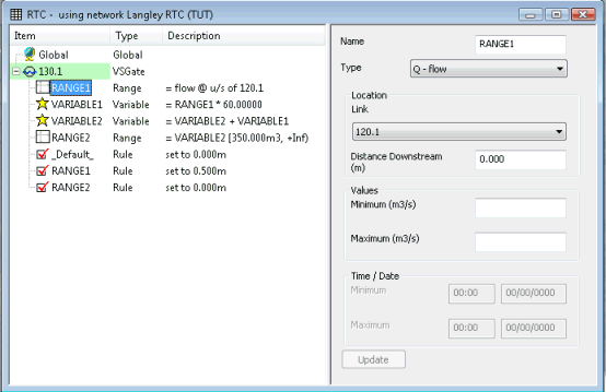
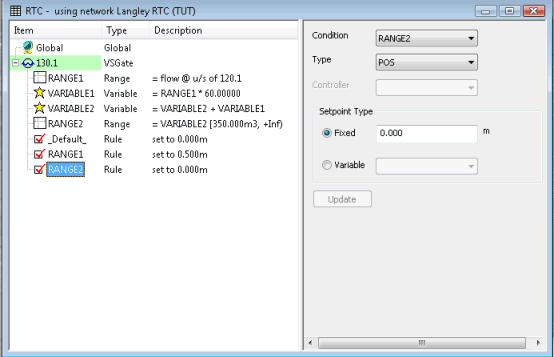
The following example models controlling the operation of a sluice gate, by measurement of the total flow through a conduit. When the total flow in the conduit reaches a given volume, the sluice gate will be closed.
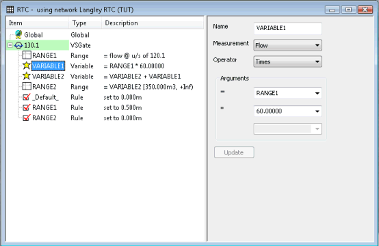
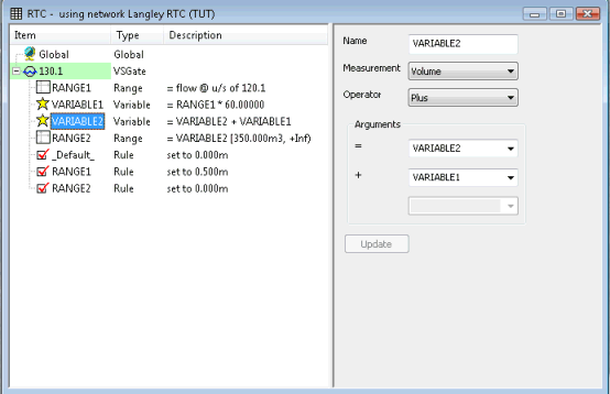
In this example, a variable is used to convert the flow measured in the control conduit to a cumulative flow over a timestep. A second variable is used to keep a total of the cumulative flow.
The example is defined by adding components to a sluice gate regulator in the RTC Window Editor.
|
Component |
Parameters |
Effect |
|---|---|---|
|
RANGE 1 |
Range type: Q - flow Location link: 120.1 Minimum: Maximum: |
TRUE if flow is between - / + infinity |
|
VARIABLE 1 |
Measurement: Flow Operator: Times Argument 1: RANGE 1 Argument 2: Constant = 60 |
Equals RANGE 1 flow multiplied by 60 |
|
VARIABLE 2 |
Measurement: Volume Operator: Plus Argument 1: VARIABLE 2 Argument 2: VARIABLE 1 |
Equals VARIABLE 1 + VARIABLE 2 |
|
RANGE 2 |
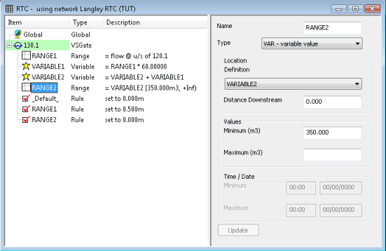
Range type: Variable Location definition: VARIABLE 2 Minimum: 350 m3 Maximum: |
TRUE if VARIABLE 2 is greater than or equal to 350 m3 |
|
RULE 1 |
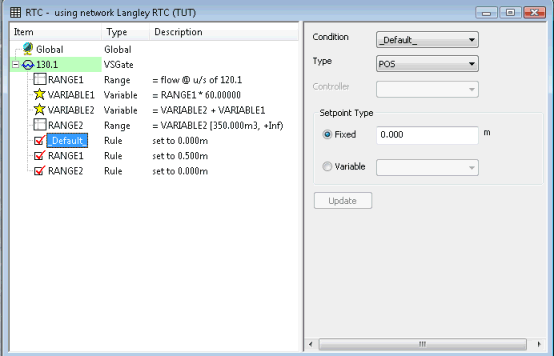
Condition: _default_ Rule type: POS Setpoint Type: FIXED 0.000 m |
DEFAULT status of sluice gate is 0.0 m |
|
RULE 2 |
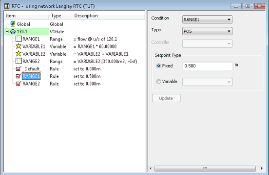
Condition: RANGE 1 Rule type: POS Setpoint Type: FIXED 0.500 m |
Set sluice gate to 0.5 m if RANGE 1 is TRUE |
|
RULE 3 |
Condition: RANGE 2 Setpoint type: FIXED 0.000 m |
Set sluice gate to 0.0 m if RANGE 2 is TRUE
|
- Range 1: Defines Link
120.1 as a control link in which flow is measured
- Variable 1: Calculates
total flow over timestep
- Variable 2: Calculates
cumulative flow through Link 120.1
- Range 2: Defines Variable
2 as a control with a minimum value of 350 m3
- Rule 1: Unless subsequent
rules are TRUE, sets sluice gate to 0.0 m
- Rule 2: Unless subsequent
rules are TRUE, sets sluice gate to 0.5 m
- Rule 3: When cumulative
flow through Link 120.1 reaches 350 m3,
sets sluice gate to 0.0 m
For a further example of an RTC Scenario, see RTC Example.
