User-Defined Controls
InfoWorks ICM allows two types of user-defined control to be specified: Compound weir/orifice and Vortex control.
This type of control is used for weirs or orifices that do not follow the standard equations, such as V-notch weirs and non-circular orifices. In this case, a table of discharges must be defined for a range of differential heads.
A compound weir/orifice is represented as a link of zero length, forming a head-discharge relationship between two nodes. The boundary condition between the link and a node is that of equal water levels. The weir crest/orifice invert level determines when the control first comes into operation. The flow characteristics are identical in both the positive and negative directions. (Use the vortex flow control link for structures with different characteristics in the two directions.).
A modular limit can be set for compound weir/orifice type of control, which uses the upstream depth to determine the free-flow from the head discharge table. A drowning factor is applied to the flow if the ratio of downstream depth to upstream depth exceeds the specified modular limit. The equations used to find the flow characteristics when a modular limit is applied is described in the Modular Limit section.
Flow Characteristics
The flow characteristics, when no modular limit is specified, are determined from the governing model equation:
|
|
where: Q - Discharge (m3s-1) f(h) - User-defined function h - Head across structure (m) |
and under free discharge conditions the head is equal to the upstream depth Du, whereas under drowned conditions the difference is Du - Dd between upstream and downstream.
The relationship between discharge and head in the positive direction is represented as a data table of up to 15 discharge values at head values equally spaced by a specified increment. The data table applies equivalently in the negative flow direction. Intermediate values are linearly interpolated from the table. If a head larger than those defined arises, then the program extrapolates linearly from the data table using the last two data values.
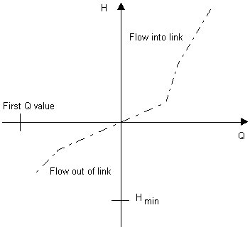
This control is similar to the compound weir, but has different characteristics for the two directions of flow.
A vortex control is represented as a link of zero length, forming a head-discharge relationship between two nodes. The boundary condition between the link and a node is that of equal water levels. The vortex invert level determines when the control first comes into operation.
A modular limit can be set for a vortex control, which uses the upstream depth to determine the free-flow from the head discharge table. A drowning factor is applied to the flow if the ratio of downstream depth to upstream depth exceeds the specified modular limit. The equations used to find the flow characteristics when a modular limit is applied is described in the Modular Limit section.
Flow Characteristics
When no modular limit is specified, the flow characteristics for the physical behaviour differ in the positive and negative directions and contain a hysteresis loop, the path through which depends on the direction of movement along the curve.

The governing model equation assumes the above linearisation of the hysteresis loop, resulting in a unique discharge for a given head:
|
|
where Q - Discharge (m3/s) f(h) - User-defined function h - Head across vortex (m) |
and under free discharge conditions the head is equal to the upstream depth Du, whereas under drowned conditions the difference is Du - Dd between upstream and downstream.
The overall relationship between discharge and head in both directions is represented as a data table of up to 15 discharge values at head values equally spaced by a specified increment. Intermediate values are interpolated linearly from the table. The discharge corresponding to a head outside the bounds of the table is determined by extrapolation.
A modular limit can be set for the user defined controls. This uses the upstream depth to determine the free-flow from the head discharge table. A drowning factor is applied to the flow if the ratio of downstream depth to upstream depth exceeds the specified modular limit. This is described in the following free flow and drowned flow equations:
Free Flow (positive or negative)
|
Condition |
|
||
|
Equation |
where: f is the specified function (values are interpolated from the user entered table of Q:y). For negative flows y2 is substituted for y1. |
Drowned Flow (positive or negative)
|
Condition |
|
||
|
Equation |
where drownf = √[ (1 - (y2 - zc) / (y1 - zc)) / (1 - m) ] or drownf = (1 - (y2- zc) / (y1- zc)) / (0.3 * (1 - m)) if the first formula gives drownf < 0.3 h1 = upstream depth of water above crest = y1 - zc h2 = downstream depth of water above crest = y2 - zc zc = crest elevation m = modular limit For negative flows switch h2 and h1 |
In free flow, the flows and levels at the user defined control will comply with the head discharge table. However in drowned flow, the table of values is altered by the drowned flow reduction factor (drownf). To encourage free flow you can set the modular limit to a high value (eg 0.999).
The second form of the drownf equation is an approximation used to avoid an infinite derivative as the downstream and upstream levels equalise. It is a linearisation of the drowning function between drownf = 0.3 and drownf = 0.0.
