Four quadrant pump curves
The pump characteristic curve defined on the Pump Curve Page for a pump object is appropriate for normal pump operation (discharge and head both positive), but not for pump operation outside of the normal zone.
During a transient event, turbining, flow reversal, speed reversal, etc. may occur. All combinations of positive and negative discharge and head should be considered.
InfoWorks TS includes eight built-in four quadrant characteristic pump curves describing pump behaviour during normal and abnormal pump operation. Three of the curves have been constructed using data from Hollander's experiments on centrifugal pumps tabulated in Wylie and Streeter (1983, 1993). An additional five have been constructed using data provided by Thorley (1991).

For turbines only one pair of Suter curves are currently available. These are based on the four-quadrant diagram given for a reversible pump-turbine in Engineering Monograph No 39 (Bureau of Reclamation, 1977) and currently have values for wicket gate openings from 100% to 20%.
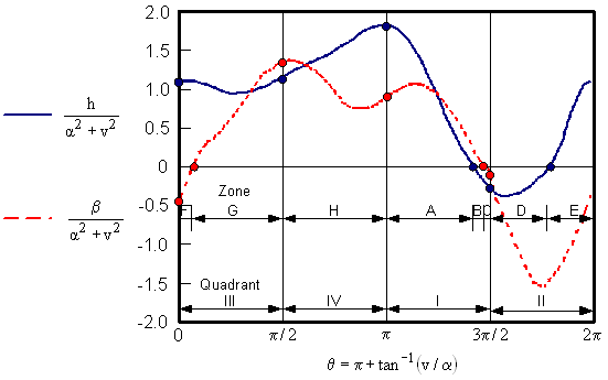
An example curve is shown below. Curves of h/(a2+v2) and b/(a2+v2) are plotted, where:
h = H/HR = Actual Head / Rated Head
v = Q/QR = Actual Flow / Rated Flow
a = N/NR = Actual Speed / Rated Speed
b = T/TR = Actual Torque / Rated Torque
The curves are plotted over a range of 0 to 2p using 89 data points at intervals of p/44 radians.

Four Quadrant Curve Example
| Quadrant | Zone | Flow (v) | Speed (a) | Head (h) | Torque (w) | Definition |
|---|---|---|---|---|---|---|
| I | A | + | + | + | + | Normal pumping |
| I | B | + | + | - | + | Energy dissipation |
| I | C | + | + | - | - | Reverse turbine |
| II | D | + | - | - | - | Energy dissipation |
| II, III | E | ± | - | ± | - | Reverse rotation pumping |
| III | F | - | - | + | - | Energy dissipation |
| III | G | - | - | + | + | Normal turbine |
| IV | H | - | + | + | + | Energy dissipation |
Table 1: Pump Operating Zones and Quadrants
The pump file to be used is determined based on the quantity of specific speed. The file associated with the specific speed closest to the calculated speed value is selected.
Specific speed is calculated as:
|
|
where: NR = Rated Speed, rpm QR = Rated flow, m3/s (gpm) HR = Rated head, m (ft) |
| Pump File | Pump Specific Speed (SI Units) |
Pump Specific Speed (US Units) |
|---|---|---|
| 1 | 25 | 1270 |
| 2 | 147 | 7600 |
| 3 | 261 | 13500 |
| 4 | 72 | 3725 |
| 5 | 85 | 4409 |
| 6 | 101 | 5203 |
| 7 | 131 | 6792 |
| 8 | 169 | 8764 |
Table 2: Built-in Four Quadrant Files

