About pumping stations
Pumps are widely used in water supply systems. Most pumps in a water supply system fall into three groups that perform the following duties:
- collection and transport of water from wells,
- distribution of clean water,
- pressure boosting in the network.
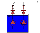
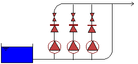
These three main types are schematically shown in the figure below.

Pumps in a Well

Pumping Station in Distribution

Booster Pumping Station
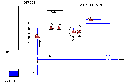
A pumping station can house several units of different types and duties, as shown in the next figure (note that there are two well pumps and four distribution pumps).

Example of a Complex Pumping Station
Pumping stations are often complex, with necessary information incomplete, data on pumps missing, etc. Modelling of pumping stations can therefore be a very complex process.
In InfoWorks WS Pro a generalised model of pumping stations is introduced. The pumping station is classified as a link, with one suction and one delivery node only. The station may have several pumps, which may be fixed speed or variable speed, active or on standby. The only condition is that all units operate in parallel - which is normal in practice. InfoWorks WS Pro assumes a check valve (NRV) on the pressure side of each pump. There is also an option to include a bypass pipe that allows flow around the station (in the same direction) when all pumps are stopped.
This concept is an alternative to the approach in which each pump is modelled separately. InfoWorks WS Pro allows the option of modelling each pump separately, by modelling each pump as a separate "pumping station".
For more information on modelling of pumping stations, see Pumping Station Control and Pumping Station Data Fields.
