Pump Control Data page (pumping station control)
Pumping stations (PST) may be permanently manned or remotely controlled. Pumps may be started and stopped by the operator or by a control device - which may be very simple or a sophisticated processor. InfoWorks WS Pro can cope with all these situations and the user can model actual control policy as it really exists, in a straightforward manner.
InfoWorks WS Pro allows the following different control modes:
- AUTO - used to model Level Controlled Pumps (LCP) or Pressure Controlled Pumps (PCP);
- FLOW – used to model discharge through the PST as a given function of time;
- PLAN - used to model Time Controlled Pumps (TCP);
- PROFILE (PROF) – used to model Level Controlled Pumps (LCP) or Pressure Controlled Pumps (PCP) working to a given target profile;
- TARGET FLOW (TFLW) - used to model Flow Controlled Pumps working to a given target profile;
- TURB - used to model turbines working on time control.
Tip: Control modes 2, 4, and 5 in the above list allow loading from live data.
Mode of control and control objects in all cases apply to the whole station, and not to individual pumps. If individual units have different modes of control (or control points), then these units should be grouped in several "pumping stations" (in the model) each with a unique mode of control.
Information on specifying more complex controls can be found in the topic About user programmable control (UPC).
Individual pumps are controlled either by variations of water level in a control reservoir (Level Controlled Pumps), or by variations of pressure in a control node (Pressure Controlled Pumps). The control node/reservoir is specified by the user on the Pump Control Page of the Pump Station Property Sheet.
Standby pumps can also be controlled by the speed of a primary pump.
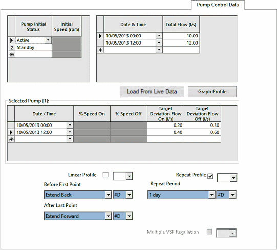
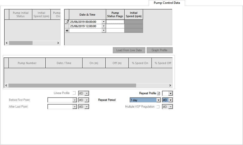
Control information is entered in the Pump Control Data Page of the property sheet.
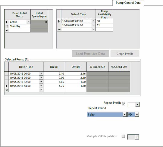
The initial status and the initial speed (for variable speed pumps) can be specified for each pump in the pumping station in the top left hand grid. The order of the pump control data corresponds with the order of the pumps specified on the Pump Data Page of the Pump Station Property Sheet.
A time varying profile of control levels and pump speeds may be specified for each pump in the bottom grid. Click the left hand side of the row in the top left hand grid to display profile details for the selected pump.
The Multiple VSP Regulation option is enabled when there is more than one variable speed pump in the pump station. Check this option to allow the pump station to regulate using all identical and available variable speed pumps; pump speeds will vary together to achieve the target. (If variable speed pumps are not identical, the pump station will regulate using the first variable speed pump and pumps identical to that pump to regulate. Other pumps in the pump station will be run at full speed.)
If the Multiple VSP Regulation is unchecked, the pump station will regulate using only the first available variable speed pump. Other pumps in the pump station will be run at full speed.
In addition to controlling the status of pumps by the pressure at a reservoir or node, the speed of a primary pump can be used to control the status of standby pumps.
The % Speed On and % Speed Off fields are used to activate a pump by reference to the current speed of a running pump. The reference pump is taken as the first active variable speed pump in the Pump Station.
If the reference pump's speed exceeds % Speed On, the subject pump will turn on. If the reference pump's speed falls below % Speed Off, the subject pump will turn off. The % Speed values are expressed as a percentage of the reference pump's maximum speed.
For fixed speed pumps, % Speed settings will override Pressure On / Off settings unless there are no active variable speed pumps, in which case Pressure On / Off settings will be used if defined.
For variable speed pumps, Pressure On / Off values must be specified, however % Speed values may be specified as well. If defined both pairs of settings will be used.
Note that reverse logic is not allowed for pumps controlled by speed; % Speed On must be greater than % Speed Off.
A time varying profile of availability status can be specified using the Pump Availability Flags in the top right hand grid, where 1 = Available and 0 = Unavailable. If there is more than one pump in the pumping station, the pump availability is entered for each pump in the order that the pumps are specified in the Pump Data Page of the Pump Station Property Sheet.
Note:
- If no availability flags are specified, the pump is assumed to be available.
- If Pump Initial Status is set to Not Available, the pump is always unavailable regardless of availability flag settings.
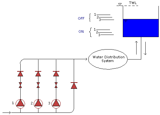
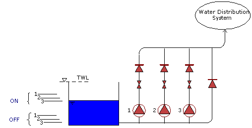
Two simple cases are shown below: a) - the most common situation and b) - a rare case in water supply.
AUTO control - "normal"
AUTO control - reverse logic
The a) case shows the most common case: as water level rises in the control reservoir, pumps are stopped one after the other (first unit No. 3), preventing overspill. When the level falls, pumps are started in reverse order. Settings "on" and "off" are constant throughout a simulation run. In practice, these settings are periodically adjusted, depending on the season and other circumstances. The user can easily make several runs, with different settings, in order to find the most suitable solution.
The basic idea of this system is "keep the reservoir full", a normal requirement. However, there are cases (admittedly rare in water supply, but common in drainage systems) where the policy is "keep the reservoir empty" - or half-empty, see figure b). Here pumps are started when the water level in the control reservoir rises to a given elevation, and stopped when it falls to a lower level. In InfoWorks this policy is known as "reverse logic" - because it is opposite to the normal one. Again, control levels for each unit are carefully selected, taking into account all facts.
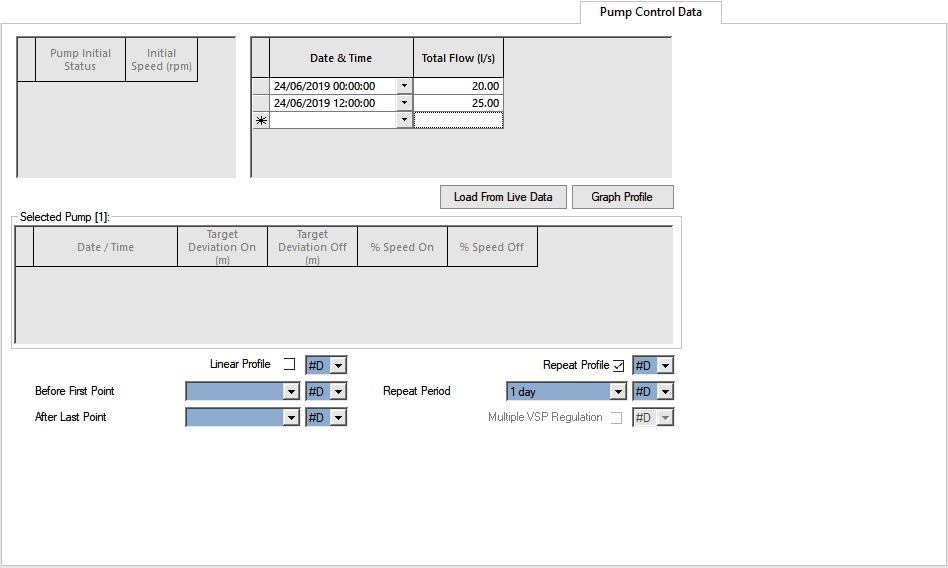
The user specifies the target discharge profile from the pumping station during the simulation period.
This mode may be useful in the calibration process, when the user has to duplicate past events in the model.
In FLOW mode the user may also specify an Override node, (which may be a node or reservoir), and Pressure On and Pressure Off values in the Pump Control Page of the Pump Station Property Sheet. If the pressure/level at the Override node exceeds the Pressure Off value at any time, the pumping station will be stopped immediately, regardless of other controls. The station will resume operation only when the pressure/level at the Override node falls below the Pressure On value.
This feature allows simulation of a real pumping station with overpressure protection, for instance.
This mode of operation is used for modelling Time Controlled Pumps. Individual pumps are controlled by setting start/stop times for each pump, in the pumping station.
The time clock in InfoWorks WS provides the necessary action during the simulation. If the scheduled time is in the middle of timestep (dt), for example, the action will be slightly postponed to the next steady-state computation.
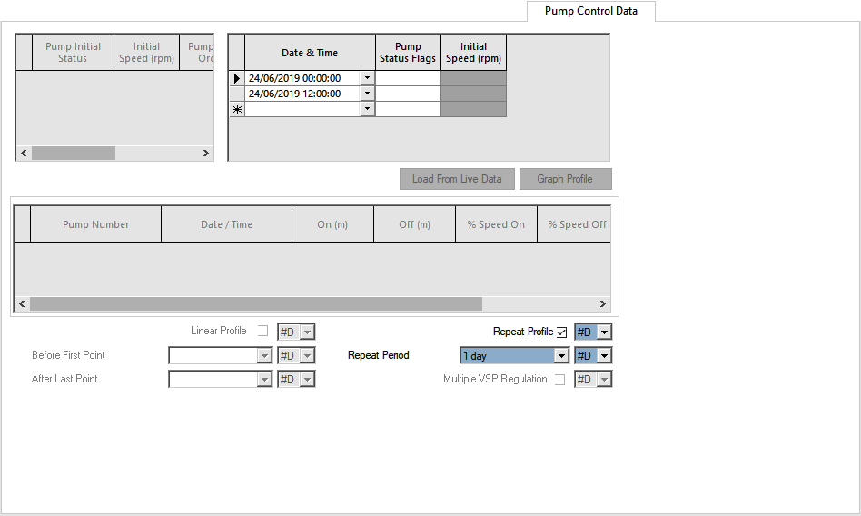
On/off status is specified by Pump Status Flags where 1 = ON and 0 = OFF. If there is more than one pump in the pumping station, the pump status is entered for each pump in the order that the pumps are specified in the Pump Data Page of the Pump Station Property Sheet.
This mode is very useful in the calibration process, when the user has to duplicate past events in the model.
In PLAN mode the user may also specify an Override node, (which may be a node or reservoir), and Pressure On and Pressure Off values in the Pump Control Page of the Pump Station Property Sheet. If the pressure/level at the Override node exceeds the Pressure Off value at any time, the pumping station will be stopped immediately, regardless of time controls. The station will resume operation only when the pressure/level at the Override node falls below the Pressure On value.
This feature allows simulation of a real pumping station with overpressure protection, for instance.
The PROFILE mode of operation is a more complex form of the AUTO mode used for pressure/level controlled pumps.
In PROFILE mode the user specifies a target pressure/level profile to be met at a Control node, (which may be a node or reservoir), specified in the Pump Control Page of the Pump Station Property Sheet.
Control information is entered in the Pump Control Data Page of the property sheet.
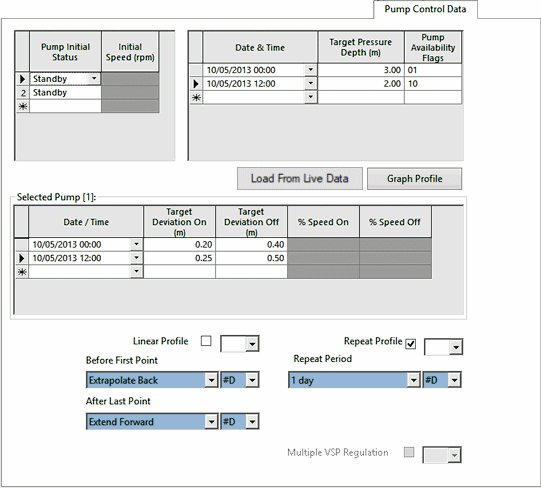
The initial status and the initial speed (only required for variable speed pumps) can be specified for each pump in the pumping station in the top left hand grid. (If a variable speed value is not specified, the pump will operate at its nominal speed). The order of the pump control data corresponds with the order of the pumps specified on the Pump Data Page of the Pump Station Property Sheet.
A time varying profile of target deviation on/off values and pump speeds may be specified for each pump in the bottom grid. Click the left hand side of the row in the top left hand grid to display profile details for the selected pump.
The Multiple VSP Regulation option is enabled when there is more than one variable speed pump in the pump station. Check this option to allow the pump station to regulate using all identical and available variable speed pumps; pump speeds will vary together to achieve the target. (If variable speed pumps are not identical, the pump station will regulate using the first variable speed pump and pumps identical to that pump to regulate. Other pumps in the pump station will be run at full speed.)
If the Multiple VSP Regulation is unchecked, the pump station will regulate using only the first available variable speed pump. Other pumps in the pump station will be run at full speed.
In addition to controlling the status of pumps to a target pressure at a reservoir or node, the speed of a primary pump can be used to control the status of standby pumps.
The % Speed On and % Speed Off fields are used to activate a pump by reference to the current speed of a running pump. The reference pump is taken as the first active variable speed pump in the Pump Station.
If the reference pump's speed exceeds % Speed On, the subject pump will turn on. If the reference pump's speed falls below % Speed Off, the subject pump will turn off. The % Speed values are expressed as a percentage of the reference pump's maximum speed.
For fixed speed pumps, % Speed settings will override Target Deviation On / Off settings unless there are no active variable speed pumps, in which case Target Deviation On / Off settings will be used if defined.
For variable speed pumps, Target Deviation On / Off values must be specified, however % Speed values may be specified as well. If defined both pairs of settings will be used.
Note that reverse logics is not allowed for pumps controlled by speed; % Speed On must be greater than % Speed Off.
A time varying profile of target pressure/depth and availability status can be specified in the top right hand grid.
The target pressure/depth is the target to be met at the Control node specified in the Pump Data Page of the Pump Station Property Sheet.
Availability status is defined using Pump Availability Flags, where 1 = Available and 0 = Unavailable. If there is more than one pump in the pumping station, the pump availability is entered for each pump in the order that the pumps are specified in the Pump Data Page of the Pump Station Property Sheet.
Note:
- If no availability flags are specified, the pump is assumed to be available.
- If Pump Initial Status is set to Not Available, the pump is always unavailable regardless of availability flag settings.
PROFILE mode is used to maintain pressure in a distribution area at a target point. It may also be used to maintain a constant level in a reservoir.
The TARGET FLOW (TFLW) mode of operation is used to model flow controlled pumps working to maintain a target flow profile.
In TFLW mode the user specifies a target flow profile to be met at a Control pipe specified in the Pump Control Page of the Pump Station Property Sheet.
Control information is entered in the Pump Control Data Page of the property sheet.
The initial speed (only required for variable speed pumps) can be specified for each pump in the pumping station in the top left hand grid. (If a variable speed value is not specified, the pump will operate at its nominal speed). The order of the pump control data corresponds with the order of the pumps specified on the Pump Data Page of the Pump Station Property Sheet.
A time varying profile of target deviation on/off values and pump speeds may be specified for each pump in the bottom grid. Click the left hand side of the row in the top left hand grid to display profile details for the selected pump.
In TFLW mode the user may also specify an Override node, (which may be a node or reservoir), and Pressure On and Pressure Off values in the Pump Control Page of the Pump Station Property Sheet. If the pressure/level at the Override node exceeds the Pressure Off value at any time, the pumping station will be stopped immediately, regardless of time controls. The station will resume operation only when the pressure/level at the Override node falls below the Pressure On value.
The Multiple VSP Regulation option is enabled when there is more than one variable speed pump in the pump station. Check this option to allow the pump station to regulate using all identical and available variable speed pumps; pump speeds will vary together to achieve the target. (If variable speed pumps are not identical, the pump station will regulate using the first variable speed pump and pumps identical to that pump to regulate. Other pumps in the pump station will be run at full speed.)
If the Multiple VSP Regulation is unchecked, the pump station will regulate using only the first available variable speed pump. Other pumps in the pump station will be run at full speed.
In addition to controlling the status of pumps to a target flow at a pipe, the speed of a primary pump can be used to control the status of standby pumps.
The % Speed On and % Speed Off fields are used to activate a pump by reference to the current speed of a running pump. The reference pump is taken as the first active variable speed pump in the Pump Station.
If the reference pump's speed exceeds % Speed On, the subject pump will turn on. If the reference pump's speed falls below % Speed Off, the subject pump will turn off. The % Speed values are expressed as a percentage of the reference pump's maximum speed.
For fixed speed pumps, % Speed settings will override Target Deviation On / Off settings unless there are no active variable speed pumps, in which case Target Deviation On / Off settings will be used if defined.
For variable speed pumps, Target Deviation On / Off values must be specified, however % Speed values may be specified as well. If defined both pairs of settings will be used.
Note that reverse logics is not allowed for pumps controlled by speed; % Speed On must be greater than % Speed Off.
The TURB mode of operation is used to model turbines. These are modelled as pumping stations working in reverse: the pumping station upstream node is treated as the turbine outlet and the downstream node as the inlet. Therefore the duty head is still positive but the duty flow and speeds are negative.
On/off status is specified by Pump Status Flags were 1 = ON and 0 = OFF. If there is more than one turbine in the pumping station, the turbine status is entered for each turbine in the order that the turbines are specified in the Pump Data Page of the Pump Station Property Sheet.
Note: pump curves are not defined for turbines, although Duty Flow and Maximum Speed values are entered in the Pump Data page of the Pump Station Property Sheet.
Turbines are provided with fixed internal curves for Francis turbines based on the Suter curve provided for transient runs. These curves are scaled for individual duty heads, flows and speeds. In hydraulic runs the speed is fixed at the maximum speed and the head/flow curve is taken at maximum efficiency of 93%, with a corresponding wicket gate opening of 75%. The Suter curve is based on a four-quadrant diagram given for a reversible pump-turbine in Engineering Monograph No 39 (Bureau of Reclamation, 1977).
Time varying pump schedules: options for extending the profile outside of the entered dates / times
When specifying time varying pump schedules at a pump station, options are available for extending the profile outside of the entered dates and times.
Option to use live data
You can load live data by clicking the Load From Live Data button (where available) and using the Link To Live Data dialog to choose your source and update the grid.
Note: If the data in the live data file is not compatible with the control data, you will be warned, and no changes will be made.
When you have finished updating, close the dialog using the X button in the top right corner.
Option to clear the grid
A quick method of clearing the grid is to use the Clear button on the Link To Live Data dialog.
