About user programmable control (UPC)
The status of the pump or valve may be controlled by a simple set of rules. For example, a pump may be switched ON/OFF depending on the time of day or on the depth of water in a reservoir. In such cases the controls can be modelled easily by defining control data on the basic control pages of the network object property sheet.
However, the regulators in a water supply system may be controlled by a more complex set of rules. For example, pump status may be controlled by the level in a reservoir, with the levels at which the pump switches on and off varying throughout the day. The modelling of complex controls can be carried out using user programmable control (UPC).
UPC allows you to change the state of control elements (regulators) such as pumps and valves based on information from sensors elsewhere in the network. For example, you can use the output from a flow meter to determine when a valve should be opened or closed. In this way, you can control flows throughout the system, improve water distribution, and optimise operating regimes for the network.
The real time control of water supply networks involves predicting the demand, modelling the hydraulic characteristics and parameters of the system, and adopting a management strategy for the whole system. UPC can use remote sensors in the distribution network to monitor flows and pressures continuously. Using telemetry, you can implement a control system that applies local operating rules to change the state of the control elements.
A model can also be subjected to a wide range of hydraulic "What if?" scenarios for numerous demand and operational events.
There are two methods by which user programmable controls can be modelled:
- UPC scripts - Flexible method of defining controls. The UPC scripts are stored as part of the control data.
- UPC scenarios - More restrictive method of defining controls. The UPC scenario is a database item separate from the control data. UPC scenarios can be converted into UPC scripts and imported into a control data object. See Updating control data from a UPC scenario for details.
About regulators
Regulators are control elements, such as pumps and valves, that can physically regulate values in the network. The status of the regulator is controlled by rules based on measured properties within the network, such as flow or depth. The purpose of the regulator is to maintain a specific target value or setpoint for some variable (for example, pressure at node or depth in a reservoir).
The following types of regulator can be represented in InfoWorks WS Pro:
| Name | Regulated Variable | Remote Regulation |
|---|---|---|
|
Pump |
On/Off, Speed (variable speed pump) |
Flow, Pressure/Level |
|
Valve |
Opening (%) |
Flow, Pressure/Level |
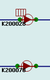
Regulators that have UPC scripts have an additional symbol theme "UPC Script Attached". This will show a grid symbol if the object has a UPC script. The image below shows two pump stations, the upper one has a local UPC script:
About controllers
Controllers take into account the change of the control point variable (flow, pressure, head) to calculate the increase or decrease in the regulator setting.
There are two options for type of controller for pressure controlled valves. These are:
- reducing / downstream- if the value at the sensor is too high, the controller will change to reduce the value. The sensor will normally be downstream of the controller.
- sustaining / upstream- if the value at the sensor is too low, the controller will change to increase the value. The sensor will normally be upstream of the controller.
