| Regulator pane |
A regulator marks the start of a block of records defining the operation
of one regulator structure in the system. Regulators in InfoWorks WS Pro are
always valves or pumps. The block can contain rules and local definitions
of control point ranges and logic rules.  Show pane Show pane
|
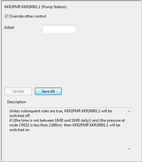
Override other control (checkbox)
|
If checked, the regulator
definition overrides any control data defined for the network object in
the control data set.
If unchecked, the regulator
definition is disabled and will be ignored. Controls defined for the network
object in the control data will be
used.
Note: In the left pane of the UPC window, the regulator text is
highlighted red if this checkbox is unchecked, and green if it is checked.
|
|
Initial
|
For valves: Initial opening
(%). If
the initial opening of a valve is left blank, an initial opening of 100%
will be assumed.
For fixed speed pumps: ON
(greater than zero) or OFF (less than or equal to zero). For variable speed pumps: Speed. If
the initial status of a pump is left blank, the pump will be assumed to
be OFF initially.
|
|
Description
|
A text description of how the regulator will operate. This description is built up from all the ranges,
logic operators, controllers,
tables, variables, and
rules defined for the regulator.
|
|
| Controller pane |
Controllers indirectly control a regulator in order to achieve a defined
setpoint.  Show pane Show pane
|
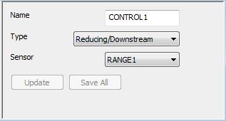
Name
|
A label that identifies a controller.
|
|
Type
|
This field is applicable only to pressure controlled valves, and describes
the controller reaction to an input signal.
Reducing/Downstream: controls
valve as a PRV - increase opening if below target and vice versa (default)
Sustaining/Upstream: controls
valve as a PSV - reduce opening if below target and vice versa
|
|
Sensor
|
A control point (node or pipe) range that is used to provide the input
signal to a controller. The controller will be ignored if the sensor does
not point to a valid range or the measurement range is not greater than
zero. Only range types of Q-Flow, P-Pressure and Z-Head can be used as
the sensor for a controller.
|
|
| Logic pane |
You can combine the output from up to four range or logic operators to give a TRUE or FALSE result.
This result can be used as the input to either another logic operator
or a rule.
If logic operators are defined under the global object, any regulator
definition can access them. Logic operators that are part of a regulator
definition are local to that regulator definition. A local definition
is used in preference to a global definition with the same label.  Show pane Show pane
|
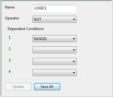
Name
|
The label that identifies the result of this logic definition.
|
|
Operator
|
A logical operator:
|
AND
|
All conditions must be TRUE for the result to be TRUE. Otherwise the
result is FALSE.
|
|
OR
|
At least one condition must be TRUE for the result to be TRUE. Otherwise
the result is FALSE.
|
|
NOT
|
If the first condition is FALSE
the result is TRUE. Otherwise the result is FALSE.
|
|
NOR
|
If all conditions are FALSE then the result is TRUE. Otherwise the result
is FALSE.
|
|
NAND
|
If any condition is FALSE then the result is TRUE. Otherwise the result
is FALSE.
|
|
|
Dependent Conditions (1 to 4)
|
Input conditions. Each of the conditions is either the label of a previously-defined
range or logic definition,
or it is left blank. At least one input condition must be given for the NOT operator and
at least two for all other operators.
|
|
| Range pane |
Ranges provide a logical output which is TRUE if the control point variable
is within the defined range (between defined minimum and maximum values)
and FALSE if it is outside the defined range. You can define the variables
at any point in the system; they do not have to be local to a regulator.  Show pane Show pane
|
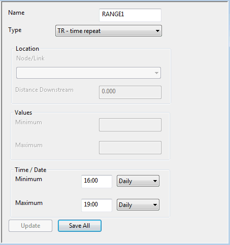
Name
|
A label to identify the range.
|
|
Type
|
The range type. Using an invalid range type will result
in the range being ignored.
| Type |
Description |
Location |
Units |
|
Z
|
Head (Level above datum)
|
Node or Reservoir
|
Z
|
|
DZ
|
Rate of change of level
|
Node or Reservoir
|
DZ
|
|
P
|
Pressure / Depth
|
Node or Reservoir
|
HEAD
|
|
Q
|
Flow
|
Link
|
Q
|
|
REG
|
Regulator State. Valve percentage opening.
|
Valve
|
See Regulators for details
|
|
PUMP
|
Binary number representing which pumps are switched on.
The first pump in the pumping station has a value of 1 if it is on,
the second pump has a value of 2 for on, the third a value of 4, the fourth
8 and so on. The value is zero for any pump that is off.
Add up the individual values for all pumps in the pumping station to
define which pumps are on or off.
|
Pump
|
seconds
|
|
VAR
|
Value of a variable, table,
range or logic record.
|
Name of a previously defined variable, table, range or logic record.
|
-
|
|
T
|
Time
|
-
|
dd/mm/yy-hh:mm
|
|
TR
|
Time repeat
Used for simulations carried out over more than 24 hours.
Minimum and maximum values can be set to be repeated daily, or can be
defined by day of the week.
|
-
|
hh:mm
|
|
|
Location
|
Specifies the control point for this range. This should match the label
of a node or link in the network. If not, the range will be ignored.
The Distance Downstream field is not used and is always disabled.
|
|
Values
|
Minimum: Minimum numeric range value. If blank, the value defaults to minus infinity.
Maximum: Maximum numeric range value. If blank, the value defaults to infinity.
|
|
Time/Date
|
Minimum: If blank, the time defaults to the start time of the simulation. A time
range should start on a major timestep.
Maximum: If blank, the time defaults to the end time of the simulation.
|
|
| Rule pane |
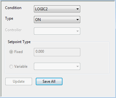
A rule controls the status of a regulator.
When the conditions on which a rule depend are TRUE the rule takes effect.  Show pane Show pane
|
Condition
|
The label of a range or logic condition previously defined for this regulator or included in the global
definitions.
The condition can be set to _default_. A default rule should be defined
before any other rules. The default rule is assumed to be TRUE.
The last TRUE rule for a regulator will be the active rule at a particular
time during the simulation.
|
|
Type
|
The rule type defines the way in which the rule operates on the regulator.
Rule types are:
|
Ctrl
|
Control
|
This rule uses a local controller.
|
|
POS
|
Position
|
This rule directly sets a value of the local regulator setting (speed or opening).
|
|
ON
|
Switch on
|
This rule can be used only with pumps.
|
|
OFF
|
Switch off
|
This rule can be used only with pumps.
|
|
|
Controller
|
For a rule using an indirect control this is the label of the controller
to be used. The controller record must have already been defined for this
regulator or in the global section.
|
|
Setpoint Type
|
Fixed: For a control rule using a controller or for
a POS rule this is the required value of the setpoint.
Variable: The name of a previously defined range, variable, or table whose value
is used as the setpoint.
|
|
| Table pane |
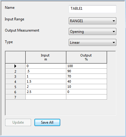
A table allows you to translate measured input values from the control
point to new output values. The input values can be the output from a
range, table, or variable. You can define a table within the global section
or in regulator definitions. The only limit to the number of tables you can define is the amount
of computer memory available.  Show pane Show pane
|
Name
|
A label that uniquely identifies the table.
|
|
Input Range
|
The name of a previously defined range, table, or variable. The input
range defines the control point at which input values are measured.
|
|
Output Measurement
|
The type of output data to be used as a regulator setting or controller
setpoint.
|
|
Type
|
Linear - InfoWorks WS Pro uses linear interpolation between the defined output values in the table data grid. InfoWorks WS Pro linearly
extrapolates from the first two values if the input value is less than
the first table entry, or from the last two values if the input value
is greater than the last table entry.
Step - No interpolation
is applied to the output values.
|
|
Table data grid
|
Define the table data here. Enter input values in ascending order. Enter
a corresponding output value for each input value. The number of records in a table is limited only by the available memory.
|
Input
|
If the input range is a time or time repeat range, you enter values
here as a date and time (dd/mm/yy-hh:mm).
For a daily range, enter the time (hh:mm) and
leave day, month and year as zero.
For a weekly range, enter the time (hh:mm) and
day (dd). Enter 01 for Monday, 02 for Tuesday and so on. Sunday is 07. Leave
month and year as zero.
|
|
Output
|
Corresponding output value. This will be used as a regulator setting
or a controller setpoint.
|
|
|
| Variable pane |
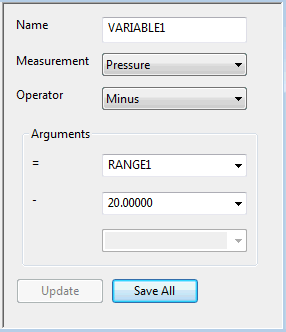
A variable allows you to combine values (from a range,
table, logic operator,
variable, or constant value) to derive another
value. All variables are set to zero at the beginning of a simulation. Variable
values are preserved from timestep to timestep, so you can use them to
accumulate statistics. Variable elements are processed in the order in
which you enter them.  Show pane Show pane
|
Name
|
An identifier for the variable. This must not be the same name as a
range, logic operator or table. However, you can have several variables
with the same variable name; the program evaluates them in the order in
which they appear in the scenario.
|
|
Measurement
|
The type of data being measured.
|
|
Operator
|
An operator to determine the way in which values will be combined.
| Operator |
Effect |
|
=
|
Variable = Argument 1
|
|
+
|
Variable = Argument 1 + Argument 2
|
|
-
|
Variable = Argument 1 - Argument 2
|
|
/
|
Variable = Argument 1 / Argument 2
|
|
*
|
Variable = Argument 1 * Argument 2
|
|
IF
|
If Argument 1 is TRUE, Variable = Argument 2
If Argument 1 is FALSE, Variable = Argument 3
|
|
TIMER
|
Sets up the variable as a timer (see below).
|
The TIMER operator allows you to set up the variable as a timer. The
value of the variable is the number of seconds since it was started (excluding
pauses). The operation of the timer is as follows:
- When the variable value is zero the timer is stopped.
- When Argument 1 is TRUE the simulation will start
the timer if it is not running.
- When Argument 2 is TRUE the simulation will reset
the timer variable to zero (stopping it running).
- When Argument 3 is TRUE the simulation will pause
the timer.
Arguments 2 and 3 may be blank.
|
|
Arguments
|
The values to be combined.
| Argument type |
Value |
|
Number
|
Number
|
|
Range name
|
Range's current value
|
|
Table name
|
Current value from table
|
|
Variable name
|
Variable value
|
|
Logic
|
0 (FALSE) or 1 (TRUE)
|
|
|
| Description pane |
This pane is used for adding a title to the UPC scenario. Access the pane by clicking the Global record.  Show pane Show pane
|
Description
|
The title for the UPC scenario.
|
|
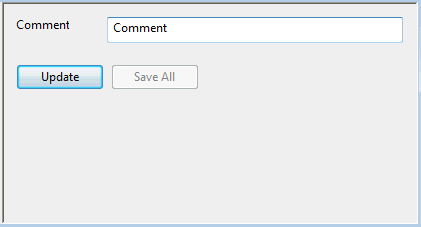
| Comment pane |
This pane is used for
adding a remark, as a reminder of the effect of the components. A comment
can be inserted at any point in the scenario.  Show pane Show pane
|
Comment
|
A remark relating to the current scenario, a regulator, or a component.
|
|
| Update (button) |
Validates the data on the current pane, then updates the scenario with the validated data. You will see a message window if the data does not pass validation. These changes are not saved unless you subsequently click the Save All button (or click Yes in the prompt when you attempt to close the UPC window without saving the changes). |
| Save All (button) |
Available if one or more panes have been updated but the scenario has not been saved. Saves all the updates made to the scenario. If updates have been made to the scenario but you have not saved them before attempting to close the UPC window, you will prompted to save them.
Note: Changes that are not validated using the Update button will be lost if you close the UPC window.
|


