UPC example (three point PRV)
The following example of user programmable control models a three point PRV.
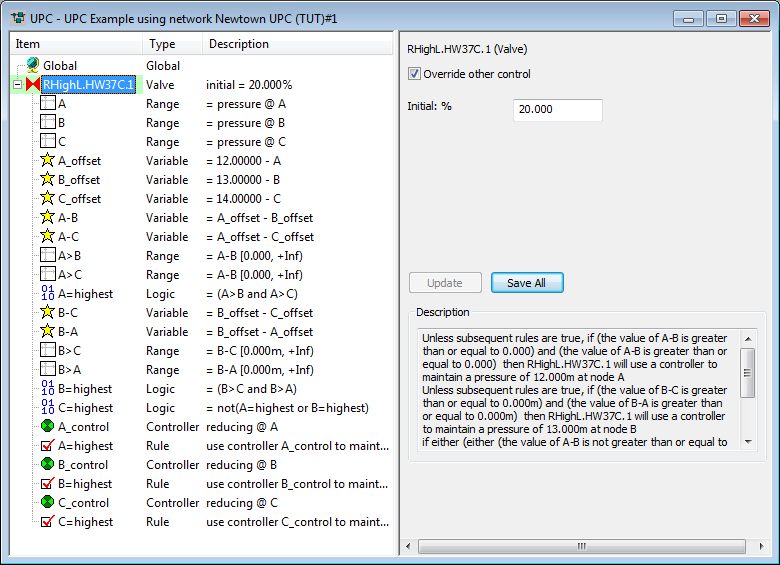
Under this scenario, pressure offsets (target pressure minus actual pressure), are calculated at sensors A, B and C. The offsets at these nodes are compared to determine the location with the biggest offset. The valve is operated to act as a PRV:
- If the offset at sensor A is greatest, the valve will operate to maintain a pressure of 12m at node A.
- If the offset at sensor B is greatest, the valve will operate to maintain a pressure of 13m at node B.
- If the offset at sensor C is greatest, the valve will operate to maintain a pressure of 14m at node C.
UPC scenario summary
| Component | Name | Parameters | Effect |
|---|---|---|---|
|
RANGE 1 |
A |
Range type: Pressure Location Node: A Minimum: |
TRUE if pressure at node A is between -infinity and +infinity |
|
RANGE 2 |
B |
Range type: Pressure Location node: B Minimum: Maximum: |
TRUE if pressure at node A is between -infinity and +infinity |
|
RANGE 3 |
C |
Range type: Pressure Location Node: C Minimum: |
TRUE if pressure at node C is between -infinity and +infinity |
|
VARIABLE 1 |
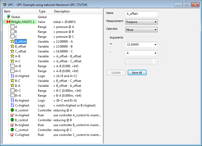
A_offset |
Measurement: Pressure Operator: MINUS Condition 1: 12 Condition 2: A |
12 - pressure at Node A |
|
VARIABLE 2 |
B_offset |
Measurement: Pressure Operator: MINUS Condition 1: 13 Condition 2: B |
13 - pressure at Node B |
|
VARIABLE 3 |
C_offset |
Measurement: Pressure Operator: MINUS Condition 1: 14 Condition 2: C |
14 - pressure at Node C |
|
VARIABLE 4 |
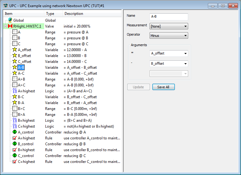
A-B |
Measurement: [none] Operator: MINUS Condition 1: A_offset Condition 2: B_offset |
A_offset - B_offset |
|
VARIABLE 5 |
A-C |
Measurement: [none] Operator: MINUS Condition 1: A_offset Condition 2: C_offset |
A_offset - C_offset |
|
RANGE 4 |
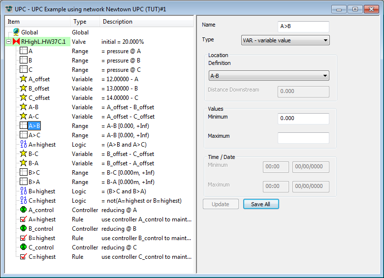
A>B |
Range type: Variable Location Definition: A-B Minimum: 0 |
TRUE if Variable A-B is greater than 0 |
|
RANGE 5 |
A>C |
Range type: Variable Location Definition: A-C Minimum: 0 |
TRUE if Variable A-C is greater than 0
|
|
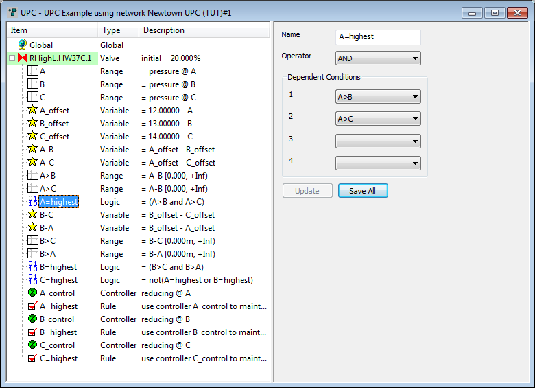
LOGIC 1 |
A=highest |
Operator: AND Condition 1: A>B Condition 2: A>C |
TRUE if Range A>B AND Range A>C are TRUE |
|
VARIABLE 6 |
B-C |
Measurement: [none] Operator: MINUS Condition 1: B_offset Condition 2: C_offset |
B_offset - C_offset |
|
VARIABLE 7 |
B-A |
Measurement: [none] Operator: MINUS Condition 1: B_offset Condition 2: A_offset |
B_offset - A_offset
|
|
RANGE 6 |
B>C |
Range type: Variable Location Definition: B-C Minimum: 0 |
TRUE if Variable B-C is greater than 0 |
|
RANGE 7 |
B>A |
Range type: Variable Location Definition: B-A Minimum: 0 |
TRUE if Variable B-A is greater than 0 |
|
LOGIC 2 |
B=highest |
Operator: AND Condition 1: B>A Condition 2: B>C |
TRUE if Range B>A and Range B>C are TRUE
|
|
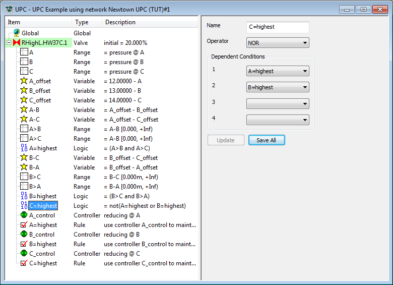
LOGIC 3 |
C=highest |
Operator: NOR Condition 1: A=highest Condition 2: B=highest |
TRUE if neither Logic A=highest or Logic B=highest is TRUE |
|
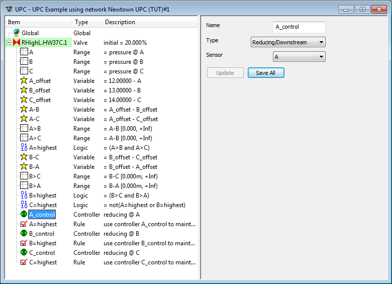
CONTROLLER 1 |
A_control |
Type: Reducing/downstream Sensor: A |
|
|
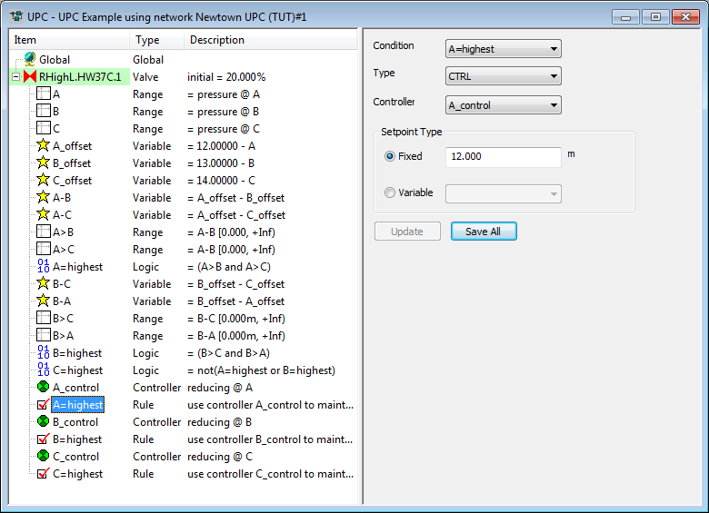
RULE 1 |
A=highest |
Condition: A=highest Controller: A_control Setpoint type: FIXED 12m |
If the offset pressure at Node A is higher than the offset pressure at Nodes B and C, the valve will be controlled as a PRV to maintain a pressure of 12m at Node A |
|
CONTROLLER 2 |
B_control |
Type: Reducing/downstream Sensor: B |
|
|
RULE 2 |
B=highest |
Condition: B=highest Controlloer: B_control Setpoint type: FIXED 13m |
If the offset pressure at Node B is higher than the offset pressure at Nodes A and C, the valve will be controlled as a PRV to maintain a pressure of 13m at Node B |
|
CONTROLLER 3 |
C_control |
Type: Reducing/downstream Sensor: C |
|
|
RULE 3 |
C=highest |
Condition: C=highest Controller: C_control Setpoint type: FIXED 14m |
If the offset pressure at Node C is higher than the offset pressure at Nodes A and B, the valve will be controlled as a PRV to maintain a pressure of 14m at Node C |
UPC scenario steps
- Insert regulator to be controlled:
 Show image
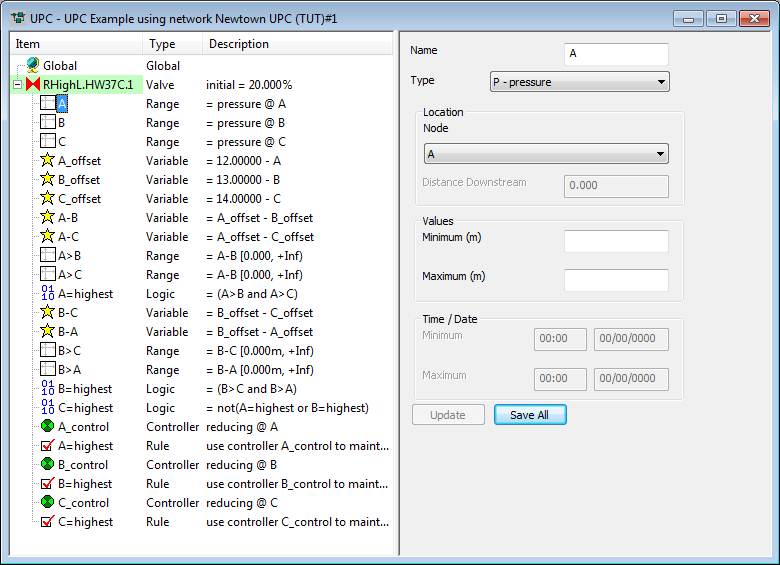
 - Define sensor nodes A, B and C by inserting ranges
of type "pressure". Show image
- Define calculation of pressure offsets at nodes
A, B and C by inserting variables. Show image
- Insert variables to be used in determining differences
between pressure offsets at A, B and C. Show image
- Define pressure offsets by inserting ranges of
type variable, using the variables defined in step 4. Show image
- Insert logic to determine whether pressure offset
is greatest at node A, B or C. Show image Show image
- Insert controllers to operate the valve. Show image
- Insert rules to determine how the valve is to
be operated. Show image