UPC table example
A table is used to describe the relationship between a set of input values and output values.
The following example shows a scenario for controlling the flow into a reservoir by adjusting the opening of a valve on the reservoir inlet according to the reservoir depth.
Under this scenario, the valve opening will be operated depending on the depth of the reservoir. As the reservoir level drops, the valve opens more to allow greater flow into the reservoir and vice versa.
The relationship between the valve opening and reservoir depth is defined in a table in the UPC scenario.
The scenario is defined by adding components to a valve regulator in the UPC window.
| Component | Parameters | Effect |
|---|---|---|
|
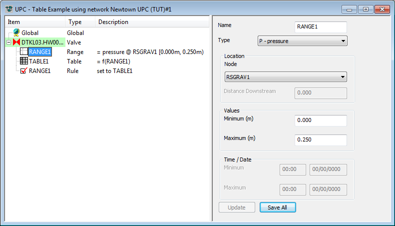
RANGE 1 |
Range type: Pressure Location node: RSGRAV1 Minimum: 0m Maximum: 0.25m |
TRUE if pressure is between 0m and 0.25m |
|
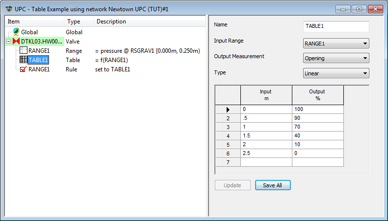
TABLE 1 |
Measurement: Opening Input Range: RANGE 1 Type: LINEAR Input/Output grid: Pressure vs Opening |
Relationship between Control point defined in RANGE 1 and percentage opening of REGULATOR |
|
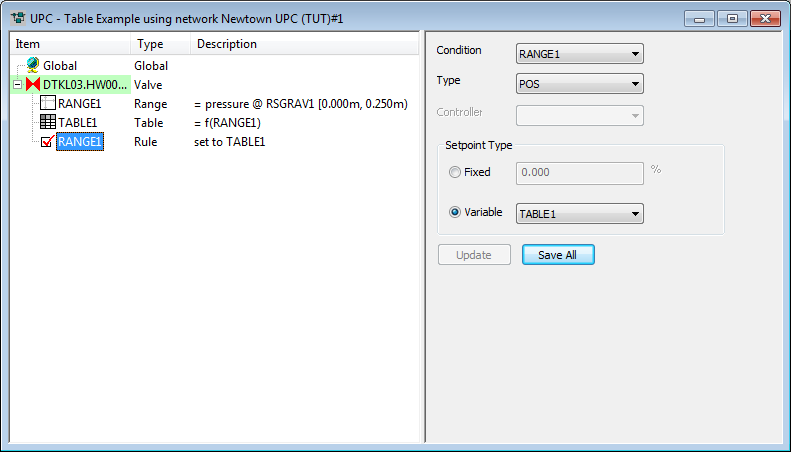
RULE 1 |
Condition: RANGE 1 Setpoint type: VARIABLE TABLE 1 |
Set valve to percentage opening from TABLE 1 if RANGE 1 is TRUE
|
- Range 1: Defines Reservoir
RSGRAV1 as the control point.
 Show image
 - Table 1: Defines the relationship
between the depth in the reservoir and the opening of the valve. Show image
- Rule 1: Operates the valve
according to the depth in the reservoir. Show image
For a further example of a UPC Scenario, see UPC example (three point PRV).
