About reservoirs
Technical details
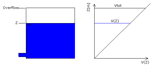
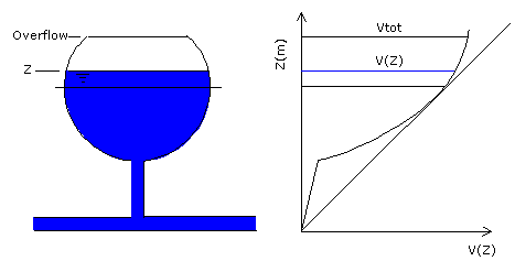
All facilities which have a free surface can be modelled using a reservoir node: service and distribution reservoirs, water towers, contact and balancing tanks, pressure-breaking chambers, shafts, etc. The important features of all of them is that the head (water level, Z) in such a node is known at one moment in time (thus allowing computation of inflow/outflow). It will remain constant during one steady-state computation, but will be changed in the next time-step (Dt) according to the continuity equation:
|
|
where: A(Z) is the area of horizontal cross-section at level Z |
Reservoirs and water towers are facilities for storing water (mostly treated). They may have one or several chambers, besides complex piping systems and accessories for inflow and outflow of water, washout, prevention of overspilling, boosting, etc., - see an example in the figure below.

A two-chamber distribution reservoir
Reservoirs may have various shapes. Common shapes are shown in the figure below. A multi-chamber reservoir could be represented either as one large reservoir or as several smaller ones, interconnected by adequate pipes and fittings (more complicated solution). This second solution is necessary whenever water levels (WL) are not the same in all chambers.
A multi-chamber reservoir can also be modelled by grouping connected reservoirs representing each chamber in a Reservoir Group. Check the Multicomponent reservoir option for the Reservoir Group to treat the group as if all its component reservoirs are part of a multiple compartment reservoir. The heads of all multi-component reservoirs will be set simultaneously to the same value except when one or more is isolated by pipe or valve closures.

A pumping station or valve used to set level in a component reservoir is treated as targeting the whole group, even if that compartment reservoir becomes isolated.

A single-chamber reservoir

A ball shaped water tower
Typical Reservoir Shapes
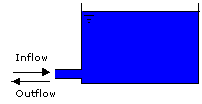
Another important piece of information is how water enters the reservoir. Typical arrangements are shown in the figure below. Note that in (c) no backflow (from the reservoir) is possible, while in (d) a non-return valve (NRV) permits rapid backflow.

a) Low Level inlet
Separate inlet / outlet pipes

b) Low Level inlet
Common inlet / outlet pipes

c) High Level inlet

d) High Level inlet with backflow pipe
Reservoir inflow arrangements
Bypass Pipe
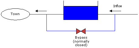
Reservoirs in distribution networks more often than not have a bypass pipe, connecting inflow and outflow pipes. This pipe is closed in normal conditions by a valve or a NRV (see figure below), but in emergencies it may be used to provide water even when the reservoir is out of use.
InfoWorks WS does not contain such a facility within the "reservoir node" item - but it may easily be modelled by adding two new nodes on each side of a reservoir with the corresponding link.

a) With a Stop Valve

b) With a NRV
Bypass pipes around reservoir
Control of Water Level
The quantity of water in a reservoir is usually controlled either by
- a float valve (FLV), which prevents overspilling or,
- a pressure-reducing valve (PRV), which keeps the water level close to a prescribed value.
The next figure shows both arrangements. For further information on Float Valves see Float Valve.

a) Reservoir with float valve on inlet to prevent overspilling

b) Reservoir with PRV on inlet to keep water level constant
Control of water level in reservoirs
Emergency Conditions
Simulating certain cases the user may encounter difficulties:
- a reservoir(s) fills up and overflows, becoming a loss,
- a reservoir is emptied and air starts to enter the distribution network.
For the first case: the water level is kept a little above the overflow elevation and the spilled quantities are recorded for later monitoring.
In the latter case, InfoWorks WS keeps the level to bottom elevation, recording the water quantity necessary to maintain this level. This gives an idea of the deficit in water in the system and allows the user to finish the simulation.
In both cases the user is warned against overspilling/emptying of reservoirs. The user can then stop the simulation to change boundary and initial conditions, switch on/off some pumps, close/open some valves or just wait for the end of the run.
