Displaying AutoCAD Text Annotations and Adjusting Values
AutoCAD file text annotations can be imported into InfoAsset Manager and displayed on the GeoPlan. Such annotations may contain precise information on the location of network objects in relation to buildings or other structures / assets and therefore be very useful for maintenance or repair purposes.
To display AutoCAD text annotations and subsequently adjust the distances:
- Open the network to be updated.
- Select Import | Import data from AutoCAD DWG from the Network menu.
This displays the Import from AutoCAD dialog.
Note: This option is only available in 64 bit versions of InfoAsset Manager.
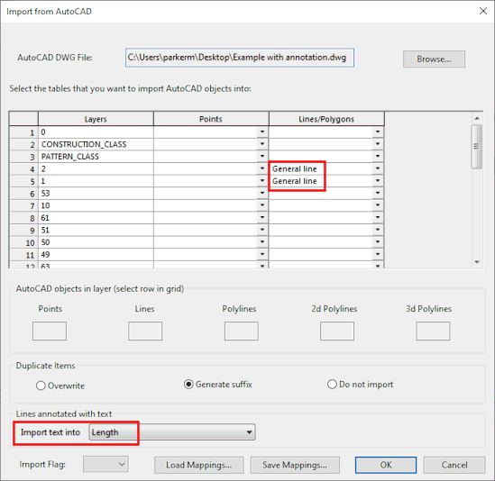
- Import the desired AutoCAD file(s) as described in the Importing from AutoCAD DWG topic. Important points are as follows:
- Select General Line in the Lines / Polygons column for the layers containing the text annotations.
- Select Length in the Import text into box. This specifies that the text should be imported into the length field of the General Line objects.
- Click OK.
- The AutoCAD data including the text annotations has now been imported. To display the text annotations on the GeoPlan:
- Right-click on the GeoPlan Window and select Properties & Themes from the context menu.
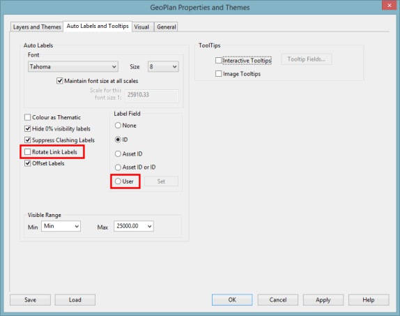
- On the Auto Labels and Tooltips page, check Rotate Link Labels, and for Label Field, choose the User option.
- Click Apply.
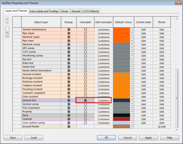
- Click the Layers and Themes page of the GeoPlan Properties dialog.
- Check AutoLabel for the General line object then click Cutomise.
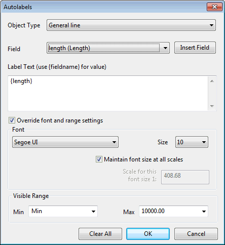
- Set the label text to display the length field. This is done by using a custom autolabel. In the Custom Autolabels Text dialog that gets displayed:
- Select General line in the Object Type list.
- Select length (Length) in the Field list.
- Click Insert Field button to add {length} to the Label Text box.
- At this stage, it is possible to choose a visible range for this custom autolabel as well as define font family and size as well as label behaviour. Refer to the Custom Autolabels Text dialog topic for further details.
- Click OK in both dialogs to save the changes and close them.
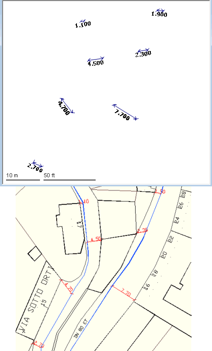
- The text annotations are now displayed on the GeoPlan, as shown in the screenshot below. At the top, the GeoPlan is showing general lines with length values, which correspond to the annotations of the DWG file below.
GIS layers can be displayed on the GeoPlan so the view can be very similar to the contents of the AutoCAD file. It is possible to print the GeoPlan or take a screenshot of it.
- If some of the measurements are proven incorrect, use the Make Measured Length tool (
 ) from the More GeoPlan Tools toolbar to adjust them. This tool allows the geometry of a line to be adjusted so it matches the length field.
 Tip
Tip The general line field containing the text annotation (Length in our case) can have a data flag associated to it. This can be done at import time by assigning a user-defined flag to the imported data or at a later date. Assigning the #D flag to that field will have an opposite effect to that of the Make Measured Length tool, i.e. it will make the measurement match the line geometry.
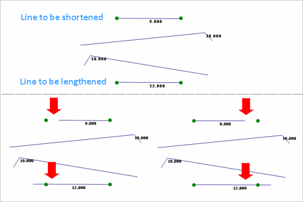
- Select the tool and click the general line to be adjusted. The adjustment is implemented on the extremity of the line that has been clicked.
The following example shows a line to be shortened (single line at the top, with an imported length of 8 m) and a line to be lengthened (single line at the bottom, with an imported length of 12 m). The red arrows show where the lines have been clicked on.
