Flap Valves
A flap valve is a control that prevents reverse flow in a conduit.
A flap valve is represented as a link of zero length, forming a head-discharge relationship between two nodes. The boundary condition between the link and a node is that of equal water levels. The valve invert level determines when the control first comes into operation.
Flow Characteristics
The simulation engine uses the following governing model equation to determine the flow characteristics in the positive direction:
|
|
where Am - average cross sectional area (m2) Vm - average velocity (m/s) Cd - discharge coefficient Q - discharge (m3/s) |
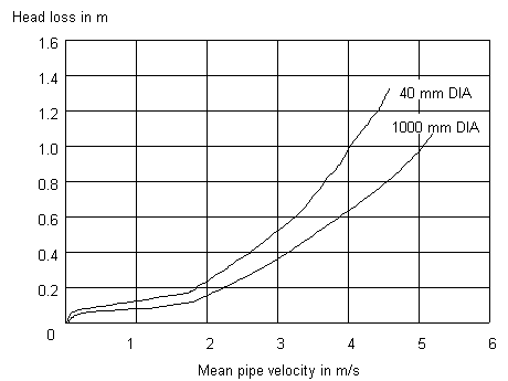
The average velocity can be defined from manufacturer's data (see Biwater, 1988) as a function of the head across the valve. In the case of a 1m diameter circular type of flap valve this is as follows:

A similar relationship is available for a 0.04m diameter valve. Data for specified diameters other than these is calculated by interpolation or extrapolation to produce analogous curves.
For rectangular type of flap valves, the area is determined by multiplying the specified width and height. This area (A) is then used in the following calculation to derive the diameter (D) of the equivalent circular area:
|
|
|
The default discharge coefficient of 1.0 corresponds to a steel check valve. A reduction of this parameter corresponds to valve materials that result in a lower head for a given flow: for example, plastic or rubber mats. Under free discharge conditions the head across the valve will correspond to the upstream depth Du and under drowned conditions the difference Du - Dd between upstream and downstream. There is a no-flow condition imposed in the negative direction.
A data table of ten points represents the relationship between average velocity and head. Intermediate points are interpolated linearly from the table. The data is extrapolated to obtain the average velocity corresponding to a head outside the bounds of the table, the behaviour in this region being approximately linear.
