Flumes
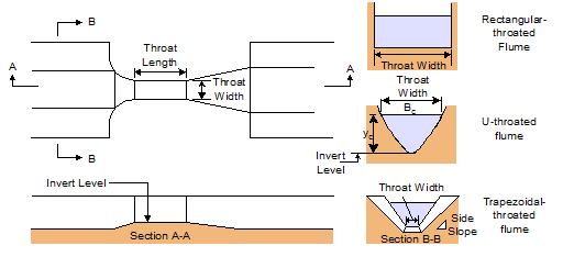
InfoWorks ICM allows you to include flumes in the network. Flumes are effectively constrictions in a channel or pipe. They are usually used to allow you to make accurate flow measurements.
Flumes in InfoWorks ICM can have one of three cross sections:
- Rectangular - rectangular flumes are simple to construct. They usually need a hump in the middle of the throat to prevent ponding or drawdown if the discharge is above or below the design discharge.
- U-shaped - always with a semi-circular invert (not parabolic, as often used for grit traps). U-shaped flumes are very common in urban drainage, for use with U-shaped channels and circular conduits.
- Trapezoidal - trapezoidal flumes are useful if you expect a wide range of discharges.
You would normally expect to use a flume that has the same type of cross section as the channels or pipes on either side.
The equations for flumes are taken from BS3680 : Part 4C : 1981.
The equations used are:
|
|
where:
where: Q is the Discharge Cdis the Discharge Coefficient. This will typically turn out to be 0.95 to 0.99 b is the Throat Width L is the Throat Length h is the Upstream Depth |
Where there is a hump in the bed at the throat of the flume, h is measured above the hump.

When the modular ratio (ratio of depth downstream against depth upstream) of the flume exceeds 75% the flume is assumed to be drowned. A nominal headloss is assumed when the flume is drowned.
The flume can only measure discharge when the flow through the throat is unaffected by the water level downstream. You would normally design flumes so they never become drowned. Nominal headloss is assumed for a drowned flume so that model calculations can continue.
The above equations are appropriate for a rectangular flume (RFLUME). Trapezoidal (TFLUME) and U shaped (UFLUME) flume use the same equations modified by shape factors. These shape factors are taken from the charts in BS3680 : Part 4C : 1981.

Remember that most controls in an InfoWorks ICM network are treated as operating in the same way hydraulically for flow in both directions. This behaviour is not appropriate for a flume, which should only have flow in one direction. It is up to you to avoid situations where reverse flow occurs at flumes in your network.
