RTC Controller Example
Controllers indirectly control a regulator in order to achieve a defined setpoint.
The following example models controlling the flow through a conduit by using an incremental controller to control the setting of a Variable Discharge Orifice.
In this example, the flow in the control conduit is measured. The setting of the Variable Discharge Orifice is changed by increments to maintain this flow at 0.580 m3/s.
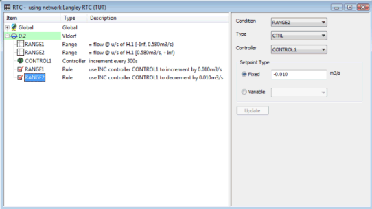
The RTC is defined by adding components to a Variable Discharge Orifice regulator in the RTC Window Editor.
|
Component |
Parameters |
Effect |
|---|---|---|
|
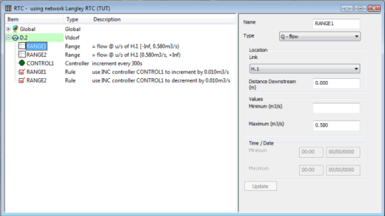
RANGE 1 |
Range type: Q - flow |
TRUE if flow in conduit H.1 is less than 0.580 m3/s |
|
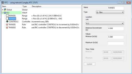
RANGE 2 |
Range type: Q - flow |
TRUE if flow in conduit H.1 is more than or equal to 0.580 m3/s |
|
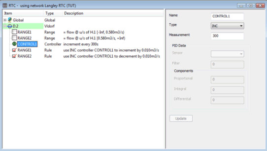
CONTROLLER 1 |
Type: INC |
Measurement interval of orifice increment equals 300 s |
|
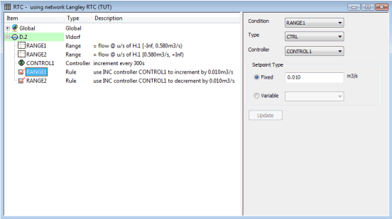
RULE 1
|
Condition: RANGE 1 Controller: CONTROLLER 1 Setpoint: FIXED 0.010 m3/s |
Increment REGULATOR by 0.01 m3/s if RANGE 1 is TRUE |
|
RULE 2 |
Condition: RANGE 2 Controller: CONTROLLER 1 Setpoint: FIXED -0.010 m3/s |
Decrement REGULATOR by 0.01 m3/s if RANGE 2 is TRUE |
- Range 1: Defines Link
H.1 as a control conduit with a maximum value of 0.580 m3/s
- Range 2: Defines Link
H.1 as a control conduit with a minimum value of 0.580 m3/s
- Controller 1: Defines
that REGULATOR increments should be carried out every 300 s
- Rule 1: If the flow in
Link H.1 is less than 0.580 m3/s, increments
orifice setting by 0.01 m3/s
- Rule 2: If the flow in
Link H.1 is more than or equal to 0.580 m3/s.
decrements orifice setting by 0.01 m3/s
