Automatic Node Name Generation
It is possible to automatically generate a Node ID whenever a new node is added to the network. By default, a new name must be typed in for every new node. Using this tool a number of naming schemes can be chosen, which reduces the length of time it takes to build network topology from scratch.
With automatic naming switched on, it is possible to prevent the node name dialog being displayed every time a node is created. See Digitising Network Objects for more details on this and other time saving tools.
The automatic naming options are set on the Name Generation dialog.
To activate automatic node name generation:
- Choose Name generation from the Network menu. This displays the Name Generation dialog.
- Switch to the Node tab, if necessary.
- Select one of the following options
- Generate an ID using the following built-in method - see below for further details
- Generate an ID using the following custom pattern - see below for further details
- Click OK to activate the option.
To disable automatic naming, follow the above procedure and select the option Do not automatically generate an ID for the new node.
Additional options allow renaming of a selection or of all the nodes in the network.
Generate an ID using a built-in method
Select this option to automatically name nodes based on coordinates.
|
Option |
Description |
|---|---|
|
UK Grid |
A name is generated based on the UK National Grid location. The name takes the form ggxxyyxynn where: gg are the letters identifying the 100 km grid square. xxyy defines the point to the nearest kilometre. xy further refines the location to the nearest 100 metres. nn is either a pair of numbers, a pair of letters , or a combination of a number and a letter, which are added to the reference to make it unique. nn starts numerically at 01 and is incremented until a unique ID is created using the sequence 00 to 99, followed by 0A, 0B, 0C ... 9Z, then A0, A1 ... AZ, then B0, B1 ... BZ, and so on until Z0, Z1 ... ZZ. This ensures that a total of 1295 unique identifiers per 100m2 can be generated. |
|
Irish Grid |
Name based on the Irish National Grid. The name takes the form Sgxxyyxynn where: S represents Ireland g is the letter identifying the 100 km grid square and the other parameters are as above |
|
XY8 |
This is an eight figure generic name generator for use with any map projection system. The name takes the form xxxxyyyy representing the x and y coordinates from the GeoPlan. In this case, InfoWorks ICM does not add a suffix to ensure the node name is unique. If the generated node name already exists, InfoWorks ICM displays a warning. It is up to you whether you add the node in a slightly different location, or add a suffix of your own to ensure a unique name. If the coordinates are too long for this format a warning will be displayed with a recommendation to review the choice of Node Name Generation built-in method. |
|
XY10 |
Ten figure version of the generic method above. |
|
XY12 |
Twelve figure version of the generic method above. |
|
XY14 |
Fourteen figure version of the generic method above. |
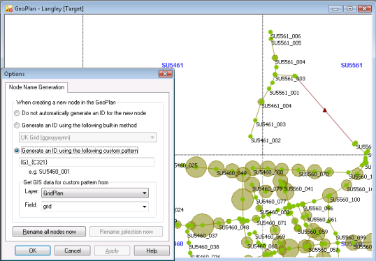
Generate an ID using a custom pattern
Select this option to automatically name nodes based on a user defined pattern.
Type a custom pattern into the box. Type in text to appear in the node name and any variable items to be used. Variable items go inside curly brackets. Variable items comprise a character identifying the source data followed by optional numbers indicating which particular digits/characters of the source data are to be used.
An example ID based on the custom ID entered will be displayed beneath the custom pattern box. (An error message will be displayed for invalid patterns.)
Valid variable items are listed below:
|
Variable Item |
Description |
|---|---|
|
{X} |
A number based on the X coordinate of the node will be appended to the node name. The default is to append the X coordinate to seven digits (counting from the right). To adjust which X coordinate digits appear in the node ID, add the coordinate digit location to the variable. Two examples are shown below. Click on the images to show the examples.
|
|
{Y} |
A number based on the Y coordinate of the node will be appended to the node name. The default is to append the Y coordinate to seven digits (counting form the right). To adjust which Y coordinate digits appear in the node ID, add the coordinate digit location to the variable. Two examples are shown below. Click on the images to show the examples.
|
|
{C} |
A count will be appended to the node name. The count will be incremented for each node that would otherwise have the same ID. The default is to append a count of two digits, e.g. Node_{C} = Node_01, Node_02, etc. To adjust the number of digits, add the number of significant places required to the variable. e.g. Node_{C4321} = Node_0001, Node_0002, etc. To adjust the starting point of the count, add "+" followed by the number from which counting is to start. e.g. Node_{C21+50} = Node_50, Node_51, etc. Note: The {C} and {?} variables can not be used in the same pattern. The {C} variable ensures uniqueness of names for nodes generated by the current user only. Use the {K} variable to generate sequence numbers on a database level. |
| {K} |
Similar to the {C} variable above. However, the sequence numbers are issued globally at the database level, ensuring that no user is given the same sequence number, thereby avoiding commit conflicts. Note: The {K} variable cannot be used with any other variables. |
|
{G} |
GIS data from a nominated layer in the GeoPlan will be appended to the node name. When using the {G} variable, the Get GIS data for custom pattern from section will become available. This section contains dropdown lists of Layers displayed in the GeoPlan and the Fields of the selected Layer. This is of particular use when using a coordinate grid layer.
To adjust which characters of the GIS Layer Field appear in the node ID, add the digits corresponding to the location of characters in the field, to the variable. The characters are numbered from left to right. e.g. from Layer field containing grid coordinates in the form SU5163 {G3456} = 5163 |
| {T} |
The object type will be appended to the node name. For example: {T} will add the type of node, for example, ' {T}_{C} will add the type of node, for example, ' |
|
{?} |
This character is used to prompt for user input when creating node IDs. When creating nodes, the node name dialog will be displayed with a "?" character in the node name. The "?" character will be highlighted, ready for the user to over-type. Multiple "?"s may be included within the curly brackets to give an indication of the number of characters to be entered by the user, however only one instance of this variable item may be used. Renaming of existing nodes can not be carried out when using the {?} variable. Note: The {?} and {C} variables can not be used in the same pattern. |
Renaming existing nodes in the network
There are two options for automatically renaming existing nodes in the network based on the Node Name Generation method selected:
- Rename all nodes now - renames all nodes in network
- Rename selection now - renames nodes selected in GeoPlan
Clicking on the rename buttons displays a Renaming dialog.
Existing Node IDs will be overwritten by the renaming process. To keep a record of existing Node IDs, check the Keep a record of the old node IDs for reference box. Choose to store old node IDs in User Text 1 or User Text 2 fields (this will overwrite any existing data in these fields), or to append the node ID information to the Notes field.
