About open channels
This is for representing conduits and aqueducts on networks.
See the Pipe calculation information
Open channels are modelled as a link with reservoirs attached at each end. This is required to ensure that there are no gaps between the pressurised and non-pressurised sections of a network.
The open channels themselves can be modelled either using time-dependent St. Venants equations or by splitting the link up into five sections, and treating each section as its own reservoir.
Which method is used in a simulation is determined by the setting of the Use Time Dependent Equations (Open Channels) option in the Simulation Defaults page.
If this option is set to "No", the link is split five sections, and each section is treated as its own reservoir as follows:
- Between the top reservoir and the first section of the open channel, flow is introduced through an orifice. The orifice properties can be defined, and as a result flow through the orifice is calculated.
- Between each section within the open channel, the Manning's equation is applied to calculate the flow. For each timestep, the Manning's equation is applied to each of the five sections within the open channel, and as a result flow is calculated between the sections.
- Between the bottom section of the open channel and the bottom reservoir, either the Manning's equation is applied to the flow into the reservoir, or flow is calculated over a broad crested weir. If a weir is defined at the downstream end of the open channel, the broad crested weir will be used to calculate flow leaving the open channel; if no weir is defined at the downstream end of the open channel, the Manning's equation will be used to calculate flow leaving the open channel.
If the Use Time Dependent Equations (Open Channels) option is set to "Yes", the open channels are modelled using time-dependent St. Venants equations. Only one value of hydraulic roughness may be assigned which uses either Colebrook-White or Manning expressions for the conveyance. The governing equations are a pair of conservation equations for mass and momentum:
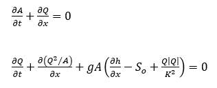
where:
Q - discharge or flow (m3/s)
A - cross-sectional area (m2)
g - acceleration due to gravity (m/s2)
h – water surface depth (m)
So - bed slope
K – conveyance
Each open channel is divided into discrete computational points regularly spaced at an interval of 20 times the channel diameter. The St Venants equations are then solved directly using a Preissman scheme and a finite difference formulation. The equations are discretised in the plane defined by the channel length and depth for water surface depth and flow and are completed with boundary conditions at the junctions with the upstream and downstream reservoirs. Inflow into the open channel is through an orifice and outflow at the bottom is either that for a broad-crested weir or, if no weir is defined, that corresponding to critical flow, calculated from the down-stream wetted area and flow width at the water surface. Open channels in InfoWorks WS Pro are allowed to spill if the water level is above the channel height at any point along the channel.
Solver
The discretisation of the governing equations in the channels results in a large system of algebraic non-linear finite difference equations to be solved simultaneously at each time level using the iterative Newton-Raphson method.
Non-linear effects may result in the time-step being automatically adjusted by progressive halvings until convergence of the Newton-Raphson method is reached. Conversely, rapid convergence may result in the time-step being doubled. The initial time-step is set to 1 second and the equations are solved from one major InfoWorks WS Prohydraulic time-step to the next, during which period the end reservoir levels remain constant. A check is also kept on inflows from the upstream reservoir to ensure it cannot supply more water than it contains. In this case the inflow is reduced to zero for the remainder of the time-dependent minor time-steps.
A relative convergence check is employed such that the change in channel depths and flows at the new time level is less than 1%.
Channel inflow
At the upstream end of the open channel, the backflow is excluded. For a full, submerged orifice the governing model equation under free discharge conditions is:
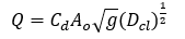
where:
Dcl - height of water level above the centroid of the orifice (m)
This is modified under drowned conditions, if the downstream water level submerges the orifice, by:
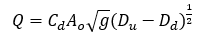
where, for both equations:
Q - discharge (m3/s)
Cd – orifice discharge coefficient = 0.884
Ao - orifice cross sectional area (m2)
g - acceleration due to gravity (m/s2)
and for the second:
Du - upstream depth above orifice invert (m)
Dd - downstream depth above orifice invert (m)
If the orifice is partially full upstream the flow characteristics are determined by a weir model:
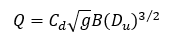
where:
Cd – weir discharge coefficient = 0.575
B – effective width of the weir (m) = Ao / (orifice diameter)
Du - upstream depth above orifice invert (m)
For a drowned weir, the equation is the same except the Du term is replaced by Du √(Du - Dd )
Channel outflow
At the downstream end of the open channel the relative levels imposed on the channel and reservoir are designed to ensure that backflow cannot occur. For a weir, the broad-crested weir discharge is:
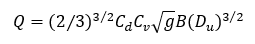
where:
Q - discharge (m3/s)
Cd – weir discharge coefficient. This is calculated using the formula below.
Cv – a dimensionless coefficient allowing for the effect of approach velocity
B – width of the weir crest
g – acceleration due to gravity
Du – upstream depth with respect to the crest
Cd is calculated using the equation:
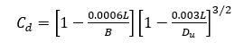
where:
L is the length of the horizontal section of the crest in the direction of flow
Cv is then calculated in terms of Cd using:
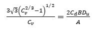
where:
A is the cross-sectional area of the approach channel below the water level
If there is no weir, the critical flow is calculated from
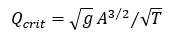
where:
A – channel wetted area
T – top width of channel flow
A control can be set for the open channel where you can define the initial level of the channel, as can be done with reservoirs.
During a simulation, any overflow that occurs along the open channel is recorded as spill, as shown the same way as reservoirs.
The open channel profile, elevation of the orifice, and inlet levels of the open channel to its connecting reservoirs can be set within the properties sheet of the open channel.
