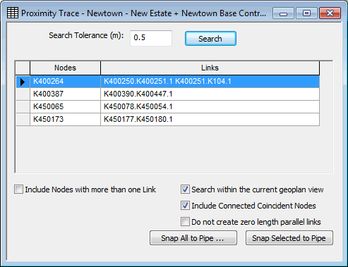
Proximity Trace View
The Proximity Trace View is used as part of the Proximity Trace procedure.
The view is displayed by choosing GeoPlan | Tracing tools | Proximity trace while a network is open.
The proximity trace tool tries to detect nodes, (usually with only one pipe connected although you can choose to search for nodes with more than one pipe connected), that lie within a certain distance of another pipe. This may indicate a connectivity problem, and the node should in fact be connected into the pipe.
- Use the Search button to look for nodes that fall within the Search Tolerance distance of another pipe (by default, only disconnected nodes, or nodes with a single pipe connected are included in the search).
- Further search options are available at the bottom of the view:
- Check the Include Nodes With More Than One Link option to search for nodes with more than one pipe connected
- Check the Search within the current geoplan view option to only search for nodes currently displayed in the geoplan
- Check the Include Connected Coincident Nodes option to search for coincident nodes connected by a link. This option is particularly useful when importing objects from GIS which are represented as nodes in GIS, but links in InfoWorks (for example, valves).
- Check the Do not create zero length parallel links option to avoid creation of a pipe with length of zero when coincident nodes connected by a link are snapped into a pipe. (For example, this option should be used when snapping in valves that have been imported from GIS point data.)
- Selecting one or more detected nodes from the list will select the nodes on the GeoPlan Window and zoom the view in on those nodes.
- Click the Snap to Pipe button to attempt to connect each of the selected nodes into the adjacent pipe.
- Click the Snap All to Pipe button for the option to automatically connect all of the nodes found by the Proximity Trace into adjacent pipes.
See Proximity Trace for more information.

