Proximity trace
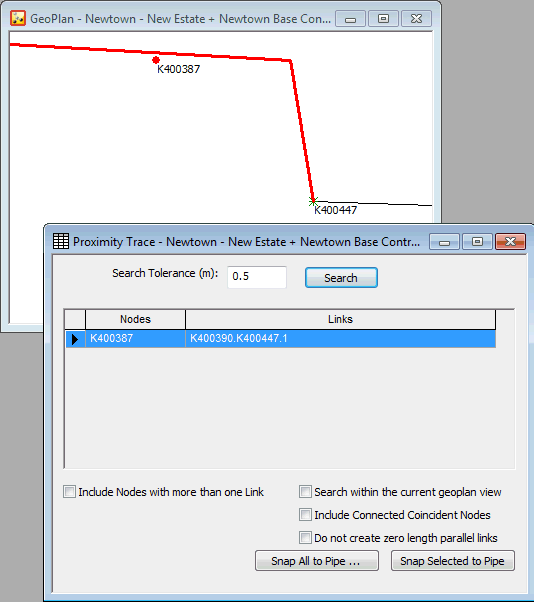
The proximity test tool tries to detect nodes, (usually with only one pipe connected although you can choose to search for nodes connected to more than one pipe), that lie within a certain distance of another pipe. This may indicate a connectivity problem, and the node should in fact be connected into the pipe.
The tool gives you the option to analyse each occurrence, and, if you wish, to automatically split the adjacent pipe and connect the node in at the nearest point.

The Tracing Process
Carrying out a Proximity Trace:
- With a network open, choose GeoPlan | Tracing tools | Proximity trace. This will display the Proximity Trace View. If you want to make subsequent changes to the network, it must be checked out.
- Set a Search Tolerance value. The default is 0.5 metres. If you want, you can carry out a trace with the default value, and then carry out further traces with higher values if needed.
- Select nodes to be included in the search by using the check box options:
|
By default, only disconnected nodes and nodes connected to a single link will be included in the search. Check the Include Nodes with more than one Link box to include nodes connected to more than one link. |
|
By default, the entire network will be searched. Check the Search within the current geoplan view box to only include nodes currently displayed in the geoplan. |
|
By default, coincident nodes connected by a link will not be included in the search. Check the Include Connected Coincident Nodes box to include coincident nodes connected by a link. This option is particularly useful when importing objects from GIS which are represented as nodes in GIS, but as links in InfoWorks (for example, valves). |
- Check the Do not create zero length parallel links option to avoid creation of a pipe with length of zero when coincident nodes connected by a link are snapped into a pipe. (For example, this option should be used when snapping in valves that have been imported from GIS point data. By default, when the second node of the point valve is snapped into the pipe, a zero length pipe parallel to the valve is created. If the Do not create zero length parallel links option is checked, the zero length pipe will be discarded.)
- Click the Search button to list un-connected nodes that lie within the Search Tolerance distance of another pipe and match the criteria selected above.
Processing Detected Nodes
Zooming in on a node
If the Search within the current geoplan view check-box is not ticked:
If you select a single node on the Proximity Trace View grid, the node and adjacent pipe will be selected on the GeoPlan Window. The GeoPlan Window will zoom in to the maximum extent possible while still showing the node and the adjacent pipe. If you select more than one node, all selected nodes and adjacent pipes will be selected on the view. The GeoPlan Window will zoom in to the maximum extent possible while still showing all the nodes and their adjacent pipes.
You can select nodes by clicking the left hand column of the grid. You can zoom in further or move around on the GeoPlan Window at any time.
Snapping detected nodes to pipes
To automatically snap all nodes detected by the Proximity search to pipes:
- click the Snap All to Pipe button. The Move Node dialog will be displayed.
- select a flag for new link lengths if required.
- use the buttons at the bottom of the dialog to select action to be taken for each node:
- OK All - Snaps all of the nodes found in the proximity search to adjacent pipes.
- OK - Snaps current node to adjacent pipe. The Move Node dialog for the next node in the Proximity Trace list will be displayed.
- Cancel - Current node is not snapped to pipe. The Move Node dialog for the next node in the Proximity Trace list will be displayed. If OK All is clicked after cancelling, only nodes after the current node in the list will be processed.
Each node displayed in the grid on the Proximity Trace View is snapped to its adjacent pipe at the nearest point on the pipe. When using OK All, the node will be snapped to the first pipe in the Split Existing Link list.
When splitting the existing pipe:
- the node is moved to the nearest point on the adjacent pipe
- the adjacent pipe is divided at that nearest point, creating two pipes that have identical parameters apart from the Length parameter. The Length is:
- recalculated from the GeoPlan if the existing Length field has the #D flag set
- calculated by splitting the existing defined Length based on where the node is placed in the existing link if the #D flag is not set. The Length field will be flagged with the flag chosen in the Move Node dialog.
- the node is now attached to the ends of the existing pipe and the new pipe
To process a selection of nodes in turn; select the rows of detected nodes in the Proximity Trace View to be processed and click the Snap Selected to Pipe button. You will be given the option to insert each selected node into its adjacent pipe in turn.

When processing coincident nodes connected by a link, snapping the nodes to pipes will result in duplicate links.
