Boundary trace
You can trace outwards from a single starting point - a selected node or link - until the tracing tool reaches pre-defined boundary points. The trace will radiate out from the starting point. Each branch of the trace will stop when it reaches bounding points of the type you have chosen, or the limits of the network.
In addition, you can choose to pause the trace if it crosses the border between two areas (as defined using the node Area Code fields) without encountering a boundary point.
The boundary trace tool uses the Boundary Trace View.
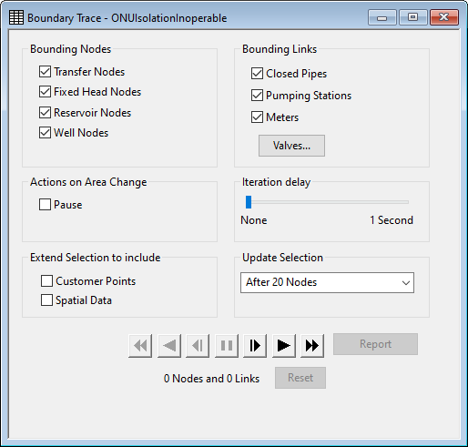
You can set options to control how quickly the trace is displayed, and how often the screen is updated. You can also control a replay of the trace using the buttons at the bottom of the view.

Boundary Trace View
Boundary Points
There are several kinds of nodes and links that you can optionally choose as boundary points, where the trace will stop. These are:
- Transfer Nodes
- Fixed Head Nodes
- Reservoir Nodes
- Well Nodes
- Closed Pipes
- Pumping Stations
- Meters
- Some or all Valve types
Valves
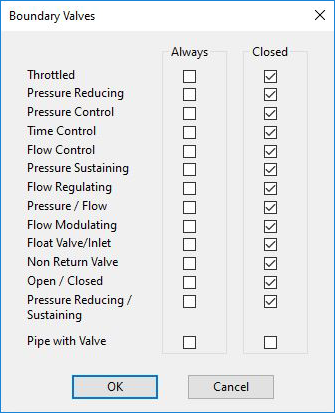
You have a number of options when choosing Valves as bounding points. Valve options are set on the Boundary Valves dialog. Access the dialog by clicking the Valves button on the Boundary Trace View.

Boundary Trace Valve dialog
The options vary depending on whether you have a control data set open.
Note: If the Has Valve check-box is set to true in a pipe to indicate the presence of a service valve, then tracing can be asked to stop at these service valves. Of course it is better to model a valve explicitly using a throttle valve or an open/close valve.
With Control Data
Each type of valve can be:
- never used as a boundary
- always used as a boundary
- only used as a boundary when the valve is closed
- any valve is considered closed if the Pipe Closed field is checked in its control data
- throttle valves (THV) are considered closed if they have a Percentage Opening value of zero
- pressure control (PCV) and flow control (FCV) valves are considered closed it they have an Initial Opening of zero and no associated control data object that can change this value
The settings for each valve can be changed independently. The default setting is that all valve types are boundaries if closed.
Without Control Data
Without a control data set associated with the network:
- the Closed option is unavailable
- the setting in the Always checkbox for all valve types from Throttled Valve down to Flow Modulating Valve (see picture) changes together. In other words, these valve types are either all included as boundaries, or all ignored.
- the default setting is that no valve types are used as boundaries
Changing Areas
The Area Code field on all model nodes will often be used to identify different District Metered Areas (DMAs) or other operational divisions in the water supply system.
It may be useful to know if the Area Code field changes (in other words a link crosses the border between two areas) without the boundary trace tool coming up against a boundary.
You have options available if the trace finds such a link
- ignore the area change
- pause the trace
Controlling the Trace
There is a set of buttons across the bottom of the view that allows you to control the display of the boundary trace. The buttons are very similar to the simulation replay buttons on the Replay Toolbar.
Before viewing the boundary trace, there are a couple of options you can set:
- Iteration Delay - an optional delay of up to one second before the boundary trace searches for the next node. Use this to slow down the display when in Play (or Reverse Play) mode
- Update Selection - controls how frequently the node and link counts are updated. This can vary from every node to every 100 nodes
The following buttons can be used to control the trace display:
|
|
Play (or Reverse Play). Use these buttons to move continuously forward (or back) through the trace. The Iteration Delay applies a time delay between nodes. The Update Selection value sets how many nodes must be added to (or removed from) the trace before the node count, link count and selection are updated. |
|
|
Single Step. Add (or remove) one node from the trace. The node count, link count and selection are updated after the step |
|
|
Fast Forward (or Back). The Iteration Delay is ignored. Update Selection sets the frequency for updating node and link count. The selection is only updated after the trace is finished or paused. |
|
|
Pause. Manually pause the trace |
| Report button | Lists valves that should be closed and valves that are ignored because they are inoperable or already closed. |
|
Reset button |
Removes the trace history and clears all the selections on the GeoPlan. You will have to select a new start node or link before repeating the trace. |
Making Network Changes
The Boundary Trace View maintains a history of the current trace, and monitors the network to see if you make any changes involving the current trace. This means that, while the Boundary Trace View is open, you can make network adjustments and then resume the trace to see what effect the adjustments have had.
If InfoWorks detects a change that affects the current trace, the trace will be automatically wound back to a point before the adjusted node or link became part of the trace.
Boundary Trace Method
To carry out a boundary trace:
- Open a network. It doesn't matter if the network is checked out or not. However, you may want to make changes while carrying out the boundary trace, and this can only be done if the network is checked out.
- you may want to open a control data set. The tracing options available are enhanced if control data is associated with the network
- choose GeoPlan | Tracing tools | Boundary trace. This displays the Boundary Trace View.
- select the appropriate boundary objects. Use the Valves button to change the options for valves if required
- decide what action you want to take if the Area Code field is different for nodes at either end of a link in the trace
- choose your trace viewing options
- use the play buttons to move forward and back through the trace
- make changes to the network if required, and either continue the trace or use the Reset button to clear the history before starting again


