The Network and associated items have to be validated before any simulation is run.
This topic assumes the network is open in the Geoplan.
Validation in InfoWorks WS Pro
To validate a network:
- Click the
 button on the Operations toolbar or choose Network | Validate network.
-
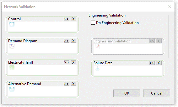
The Network Validation dialog is displayed:
- Click .
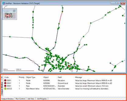
- The results of the validation are displayed in the Output window. Both errors and warnings are displayed in this window.
 - Errors - action necessary
 - Warnings - action may be required
 - Information only - no further action needed
Errors have to be corrected before any simulation can be run.
Investigating messages in the Output window
Example to illustrate how to investigate the messages displayed in the Output window.
Several options are then available to investigate the messages of the Output window.
Locating in the GeoPlan the object the Output window message relates to
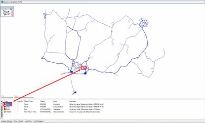
- Single-click the error or warning to highlight the corresponding network object on the GeoPlan view.
Locating in a grid the object the Output window message relates to
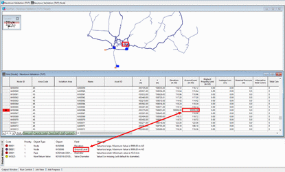
- Double-click the error or warning you wish to investigate in more detail. The appropriate grid view is displayed, with the cursor on the relevant field.
Opening the relevant grid or the property sheet for an object with a related message in the Output window
- Right-click an error or warning and select Go to grid view or Go to property page to display the appropriate grid view or property sheet.
Scrolling through the messages in the Output window
- With a Grid view open, select Network | Next error (F4) or Network | Previous error (Shift-F4) to move between the errors and warnings in the grid views. Alternatively, select another error or warning by double-clicking another item in the Output window.
Practical example of validation
We are now going to illustrate network validation using our example network.
- Open the network:
- Right-click the 'Newtown Validation' network and select Open.
- The network is displayed in the GeoPlan view.
- Select Validate network from the Network menu.
- The Network Validation dialog is displayed. If you click , the network is validated to make sure you can run a simulation with it.
- The network is validated and the Output window is displayed. There are 4 errors. Objects causing errors are highlighted in red on the GeoPlan.
- Correct the errors:
- The errors indicate that the soffit level for two connected conduits would be above the ground level of the shared node.
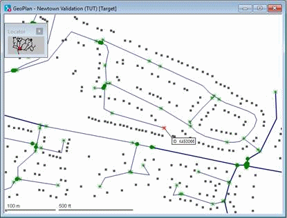
- Click the E9001 code for node K450066 and the object causing the error will be highlighted in red on the GeoPlan.
- You can, if you prefer, single-click a message to highlight the corresponding object on the GeoPlan. Right-click the GeoPlan and select Find selection.
- Select the Properties tool
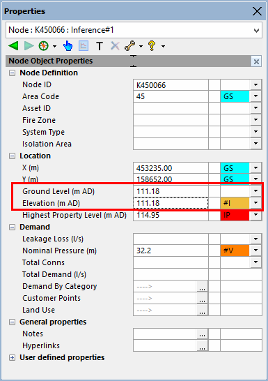
 from the Tools toolbar and click the node. The node properties are displayed. The ground level and elevation are shown as 99999 m, which is clearly wrong.
 - Check the ground level and elevation of the node immediately to the north (K450032). This is shown as 111.18 m. Redisplay the node properties for K450066, click the Ground Level field and change the value to 111.18 m. Enter the same value for the elevation.
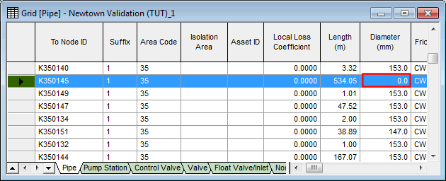
- Double-click the last E9001 error message, so that the Link grid is displayed. The
highlighted pipe has a diameter of 0 mm. The row immediately below shows
that the other pipe for which the 'From' node is K350145 has a diameter
of 153 mm. Five rows below, the pipe with a 'To' node of K350144 also
has a diameter of 153 mm. Replace the 0 mm value by clicking the Diameter
cell and entering a value of 153 mm. Close the grid view by clicking the
 button.
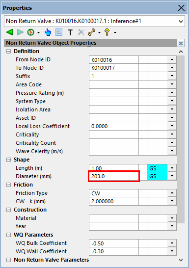
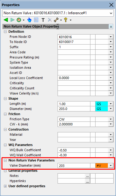
 - Click the E0325
error and find the non-return valve on the network. Use the
 tool to display the valve's properties. The pipe Diameter is shown as 203 mm.
- In the Non
Return Valve Parameters section, change the Valve
Diameter from 0 to 203 mm.
- Use Network | Validate network to revalidate the network. This time there should be no errors. If any error message is still generated at this stage, click the following link to find advice on how to solve the related issue(s).
- Close the Output window by clicking the
 button in the top left of the window.
- Commit the network (because the changes are now complete):
Right-click the uncommitted network icon in the Model Group window and select Commit changes to master database.
You are given the opportunity to enter comments relating to the network. Enter a comment and click OK.
The network is committed. You can close the GeoPlan view by clicking the button in the top right corner of the window.

