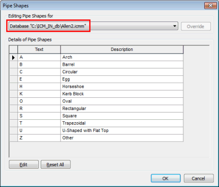
Editing Pipe Shapes
Pipe Shape information can be viewed and edited on the Pipe Shapes Editor.
The list of pipe shapes displayed in the editor grid corresponds to the Pipe Shapes choice list of the chosen CCTV Standard, set from the Standards and Choice Lists Dialog.
To edit database pipe shapes:
- Select Database management | Pipe shapes from the File menu (available when no networks are open). This displays the Pipe Shapes Editor.
To edit pipe shapes for the current network:
- Select Pipe shapesfrom the Network menu. This displays the Pipe Shapes Editor.
- In the Editing Pipe Shapes for section, select the Network option. If there is no Network option, click Override to create new settings for the current network.
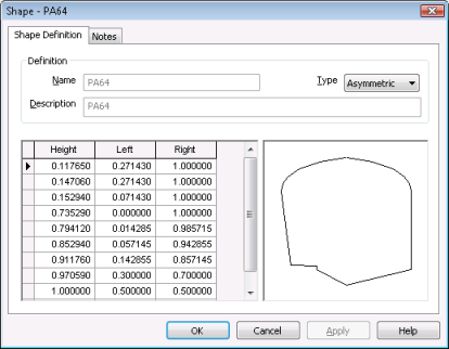
- Double-click on a Pipe Shape in the grid to view or edit the shape. This will display the Pipe Shape Property Sheet. See Pipe Shape Data Fields section below for editing details.
- Once the viewing/editing is finished, click OK.
This Pipe Shape information, in conjunction with pipe Height and Width data will be used to display a Shape Diagram for individual pipes on the Dimension Page of the Pipe Property Sheet (tabbed Property Sheet, NOT Object Properties Window).
Pipe Shape Property Sheet
The Pipe Shape Property Sheet contains two pages:
- Shape Definition Page: used to view and edit Pipe Shape parameters (see below)
- Notes Page: used to enter any relevant information
Pipe Shape Data Fields
The table below describes the use of the fields on the Shape Definition Page of the Pipe Shape Property Sheet.
|
Data Field |
Description |
||||||
|---|---|---|---|---|---|---|---|
|
Name |
Pipe shape code defined in the Standards and Choice Lists Dialog. |
||||||
|
Type |
Dropdown list of:
|
||||||
|
Description |
Pipe Shape description defined in the Standards and Choice Lists Dialog. |
||||||
|
Shape Description Grid |
Used to define pipe shapes of type Asymmetric or Symmetric. The shape is described using values between 0 and 1. It is then scaled using the Height and Width values entered for the Pipe.
|
||||||
|
Shape display |
Displays the shape selected from the Type dropdown list. For user defined shapes, the display sketches the defined shape. |