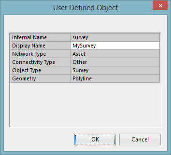
User Defined Object Grid
The Users Defined Object Grid is used to add a new user defined object or to view and edit existing user defined objects.
The dialog is displayed when the New Object button or the Edit Object button is clicked on the User Defined Objects Dialog.
The table below summarises the options available in this grid.
|
Option |
Description |
|---|---|
|
Internal Name |
Object internal name. Name must starts with a letter and cannot contain spaces, characters or upper case text. |
|
Display Name |
Object external name. This is the name of the user defined object that will be displayed throughout the InfoAsset Manager interface. For example this will be the name of the tab that will lists all the user defined objects of this type in the relevant grid on the Network Object Grid Window. |
|
Network Type |
Network type the user defined object will apply to. Available options are:
|
|
Connectivity Type |
Object connectivity:
Available types of user defined objects corresponding to all the possible combinations between Connectivity Type, Object Type and Geometry are shown in the table below. Please note that setting the Connectivity Type to Node or Link automatically sets the Object Type to Asset and Geometry to Point and Polyline respectively. |
|
Object Type |
Type of user defined object:
|
|
Geometry |
Object geometry:
|
Newly created but not saved user defined objects and user defined fields will have a green background colour in the grid.
The following table shows the available user defined objects, as well as the Network Object Grid Window they will appear in.
|
Connectivity Type |
Node |
Link |
Other |
||||||||||||||||||||
|
Object Type |
Asset |
Asset |
Asset |
Survey |
Repair |
Zone |
Incident |
Other |
|||||||||||||||
| Geometry |
Point |
Polyline |
Point |
Polyline |
Polygon |
None |
Point |
Polyline |
Polygon |
None |
Point |
Polyline |
Polygon |
None |
Polygon |
Point |
Polyline |
Polygon |
None |
Point |
Polyline |
Polygon |
None |
|
Network Object Grid Window |
Zone Grid 
|
||||||||||||||||||||||


