Channel Shape
Channel Shapes are used to define a Channel cross section. Profile shape and roughness information from a Channel are saved as a separate Channel Shape object in the Master Database. These saved shapes can then be re-used in other Channel objects.
This is particularly useful if, for example, you are modelling a surface drainage network made up of man made channels with a standard profile.
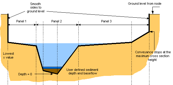
Channel Shapes may be used to define a simplistic representation of a river channel cross section. The channel cross section is divided into a series of panels. In each panel the flow is one dimensional and is calculated independently, however flow can spill from one panel to another. You define a set of records along the cross-section, beginning at the left hand side of the channel (when looking from upstream node to downstream node).
For detailed modelling of river channels, use the River Reach object.
Click on the image below to show a diagram of the typical representation of a river cross section.
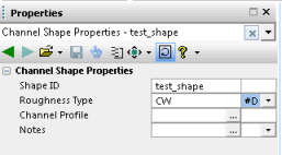
Channel Shape Properties can be seen in the Object Properties Window. The screenshot below shows a cross section in InfoWorks ICM, in the Shape ID property of the channel.
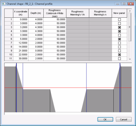
Select the Channel Profile field of the Channel Shape.
Depth is the distance above the invert level.
Data can be copied in to the cross section data fields from software such as Excel. To do this, all four columns for X Coord, Depth, Rough and New Panel must be included. For 'new panel' any non zero value will tick the relevant box.
To create a new Channel Shape object
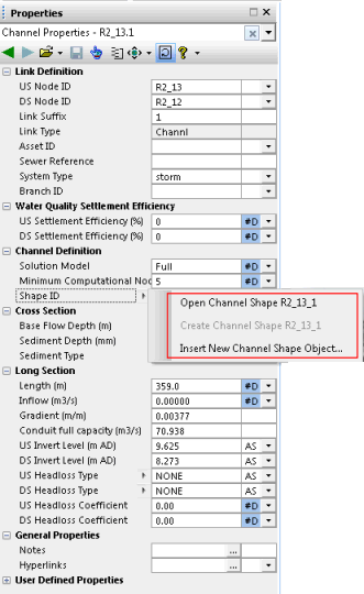
- Open the Channel Property Sheet and click on the
 button to the left of the Shape ID property.
 Tip
Tip You can also create new channel shapes in the Channel tab of the Links grid window. Type in a new channel shape name in the Shape ID cell of the channel of interest.
- Select Insert New Channel Shape Object
- The Add New Channel Shape dialog is displayed. Enter a name for the new Channel Shape (maximum 35 characters) and click on OK. If the name you chose was not unique, you will be prompted to enter a unique name.
- The Object Properties Window displays the properties for the new Channel Shape object. For Channel Profile and Notes, click on the
 button to access the Profile and Notes forms respectively, where you can enter data.
 - When you are done, click on the Save button of the Object Properties Window toolbar to save your changes.
To load an existing cross section shape into a Channel object
- On the Object Properties Window of the Channel of interest, click on the Shape ID dropdown list
- Select the desired channel shape from the list
- You can then click on the
 button and select Open Channel Shape to visualise the detail of the parameters (shape ID, roughness type and channel profile) and amend them if necessary.
 - If you have made some amendments, click on the Save button of the Object Properties Window toolbar.

Remember that when you load an existing shape, you are creating a link to the stored shape, therefore any future changes made to the stored shape will also be passed on every Channel that has that shape ID.


