Compensation for Unmodelled Pipes
You can carry out storage compensation to ensure that surcharging and flooding is not over predicted due to some smaller pipes and household connections not being included in the model. These pipes provide a volume of storage that is compensated for in the model by increasing the size of manholes.
There are three methods for applying additional storage, which are all very similar. They are:
- InfoWorks Default
- WaPUG User Note 15
- User Defined
The InfoWorks Default and WaPUG User Note 15 methods only differ in the calculation of the foul only connections. The WaPUG User Note 15 method uses a fixed consumption rate, whereas the InfoWorks Default method uses population only. The User Defined method allows you to specify all the parameters.
There is a worked example below that shows the calculations involved in the WaPUG User Note 15 method, but treated as a User Defined method so you can see the underlying values and calculations used and the steps involved.
Instructions
The process has two parts. You must first set up the parameters used for storage compensation, and then carry out the compensation itself on selected sections of the network.
Setting Up
To set up the storage compensation parameters:
- With a network open, select Storage operations | storage options from the Model menu. This displays the Storage Options dialog.
- On the Storage Compensation Page, check the checkbox for your chosen method
- InfoWorks Default or WaPUG User Note 15:
- No further setup required
- User Defined:
- Click Define. This displays the Storage Compensation Definition dialog
- Set up the required parameters. Follow the procedure in the worked example below.
- Click OK on the Storage Compensation Definition dialog.
- If required, choose a user defined flag to mark all values changed when the compensation is applied. You can display the User Defined Flags dialog and create a new flag if you want.
- Click OK on the Storage Options dialog. The parameter setup is now complete.
Once you have set up the storage compensation parameters, you still have to apply storage compensation to the network. You can only apply compensation to selected objects. This serves two purposes:
- an additional level of protection to stop you making sweeping changes across the network
- gives you the ability to use different storage compensation parameters for different areas of the network
Applying Compensation
To apply storage compensation:
- Set up the storage compensation parameters as described above.
- Select objects in the network.
- Choose Storage operations| Storage compensation from the Model menu. You are given the option of aborting the process.
- Additional storage is calculated and applied in the two Storage Compensation fields for each of the selected nodes. If you chose to apply a flag, then the flag is set for each of these fields.
No changes are made to the physical parameters of the nodes. All compensation is added to the Storage Compensation fields. With sensible use of flags it should be easy to check the sense of the numbers and change them if necessary.
Worked Example
One of the methods implemented by InfoWorks to compensate for additional storage in unmodelled pipes is the WaPUG User Note 15 method. See Chapman R.E. (1996).
The following set of calculations shows how additional storage is calculated using the User Note 15 method. The steps are shown for setting up the parameters as a User Defined method, although in practice you will never have to do this for this method. You will simply check the WaPUG User Note 15 checkbox on the Storage Compensation Page of the Storage Options dialog.
The calculations are based on a subcatchment and pipe with the following characteristics:
- Catchment area = 5 hectares
- Paved area = 20%
- Roofed area = 10%
- Pipe length = 200 metres
- Population = 500
- Additional foul flow = 0.6 l/s.
- Upstream ground level = 22.22
- Upstream invert level = 20.45 m
- Downstream invert level = 19.92 m
- Pipe diameter = 375 mm
- Average connection length = A / 4L = 50000 m2/ 4 x 200 m = 62.5 m
- Maximum connection length
- = 0.5 x (depth to soffit / pipe slope)
- = 0.5 x (1.395 / 0.00265) = 263 m
A minimum connection length of 5 metres is assigned to prevent it becoming unrealistically short.
To start, select Storage operations | Storage options from the Model menu. You must have a network open. This displays the Storage Options dialog.
On the Storage Compensation Page, check the User Defined checkbox and then click the Define button. This displays the Storage Compensation Definition Dialog dialog.
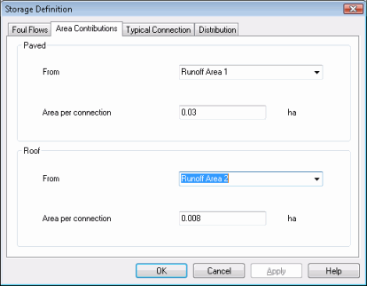
The number of paved connections is calculated assuming one connection per 300 m2 of connected paved area. The number of roof connections is calculated assuming one connection per 80 m2 of connected roof area. Both these assumptions can be defined on the Area Contribution Page. Therefore in this example there are 33.3 paved and 62.5 roofed connections.

Figure 1: Storage Compensation Dialog - Area Contributions Page
The next task is to calculate the foul only connections. These are derived from two sources:
- population - the number of connections is based on the assumption of four persons per dwelling
- additional foul flow - the number of connections is based on the assumption of 0.0093 litres per second of additional foul flow per dwelling. 0.0093 litres per second is based on four persons per dwelling and 200 litres per head per day.
The number of connections calculated for the roof area is deducted from the foul connections to avoid double counting.
So in this example the number of foul connections is:
Population + additional foul flow - roofs
= 125 + 64.8 – 62.5
= 127.3 connections
The foul only connections are converted into an equivalent connected area by assuming a housing density of 35 dwellings per hectare (or 0.02857 hectares per dwelling.) A connection length can then be calculated as before:
127.3 connections
= 3.637 hectares
= 45.46 m connection length.
The number of persons per dwelling, flow per person and housing density can be changed on the Foul Flows Page.

Figure 2: Storage Compensation Dialog - Foul Flows Page
The total number of connections and appropriate lengths are then multiplied and summed for the road, roof and foul connections.
Therefore in this example the total length is:
(Paved connections + roof connections) x average connection length + foul connections x foul connection length
= (33.3 + 62.5) x 62.5 + 127.3 x 45.5
= 11779.7 m
This total length is then multiplied by half the area of a 100 mm pipe to give the total un-modelled storage.
Half area of 100 mm pipe = 0.0039 m2.
Therefore total un-modelled storage = 46.25 m3.
You can choose the size of the typical pipe and how typically full it is on the Typical Connection Page.

Figure 3: Storage Compensation Dialog - Typical Connection Page
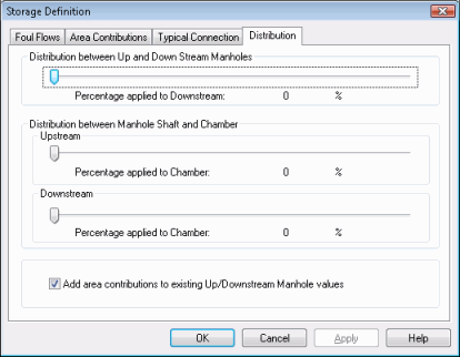
You then decide how this 46.25 m3 of storage is distributed between the up or downstream manholes and between the shafts and chambers of these manholes using the Distribution Page. By default, all the volume is applied to the upstream shaft area.

Figure 4: Storage Compensation Dialog - Distribution Page
In this example the shaft depth (ground level – pipe soffit level) = 1.395 m. Therefore the area of the shaft should be increased by
46.25 m3 / 1.395 m = 33.15 m2.
Storage compensation is then carried out using the process described earlier in this topic.
Once calculated, the additional area is automatically applied to the storage compensation fields of the Additional Storage section of the Node Property Sheet for each of the specified manholes.
