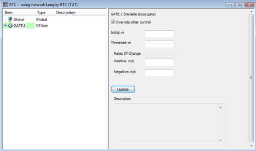
RTC Window Editor - Regulator Pane
A regulator marks the start of a block of records defining the operation of one regulator structure in the system. The block can contain rules and indirect controllers and can also contain local definitions of measurement ranges and logic rules.
The Regulator pane contains the following fields:
|
Initial |
For continuous regulators, this is the initial position of the regulator in metres. For Variable Speed (VspPmp) pumps, this is the initial flow (m3/s) of the pump. For Variable Frequency Drive (VfdPmp) pumps, this is the pump's initial speed (rpm). For Fixed Discharge (FixPmp), Archimedean Screw (ScrPmp) and Rotodynamic (RotPmp) pumps, this is the initial operating state of the pump which can be specified as: -1 (off), 0 (undefined) or 1 (on). |
|
Threshold |
The minimum action that can be performed by the regulator for this event. If the field is left blank the threshold will be determined from the network link record. Not applicable to Fixed Discharge (FixPmp), Archimedean Screw (ScrPmp) and Rotodynamic (RotPmp) pumps. |
|
Rate of Change: Positive |
The rate at which a regulator goes from one state to another in a positive direction. For example, the rate at which a gate opens or the crest of a weir rises. If the field is left blank the rate of change will be determined from the network link record. Note: the decimal precision of the rate of change field of a network object, (editable on the property sheet or grid window), is greater than that of the field on the RTC Regulator Pane. To use the greater decimal precision, leave the RTC field blank and use the network object fields. |
|
Rate of Change: Negative |
The rate at which a regulator goes from one state to another in a negative direction. If the field is left blank the rate of change will be determined from the network link record. Note: the decimal precision of the rate of change field of a network object, (editable on the property sheet or grid window), is greater than that of the field on the RTC Regulator Pane. To use the greater decimal precision, leave the RTC field blank and use the network object fields. |
|
Description |
A text description of how the regulator will operate. This description is built up from all the Ranges, Logic operators, Controllers, Tables, Variables, and Rules defined for the regulator. |
|
Override Other Control checkbox |
The status of the Override Other Control option affects whether the switch on levels in the network pump data are used in a simulation or not. The option is only relevant for pumps; the setting is ignored for other regulator types.
The regulator text (displayed in the left hand pane of the RTC Window) is highlighted red if the Override Other Control checkbox is unchecked, and green if it is checked. 
Note
The switch off level, specified as part of a pump's properties, will always be used during a simulation.
|

