Rotodynamic Pumps
A rotodynamic pump is represented as a link of zero length, forming a head-discharge relationship between two nodes. The boundary condition between the link and a node is that of equal water levels. The pump switch-on level determines when the control first comes into operation; the pump will continue running until the upstream water level drops below the lower switch-off level.
During a simulation the pump status is updated every major time-step. If, at a minor timestep, the pump status is on but the upstream level drops below the switch-off level an intermediate switch-on state is entered; this conserves volume.
Pump Characteristics
The flow characteristics in the positive direction are determined from the pump head-discharge curve.
The governing model equation assumes a fixed discharge monotonically so the simulation engine may determine a unique discharge for a given head. The equation is as follows:
|
|
where Q - discharge (m3/s) f(h) is a user-defined function given by a series of values relating head to discharge h is the head across pump (m). The head is equal to the difference between downstream and upstream water levels. |
The pump connects two nodes, representing the water level upstream and downstream of the rotodynamic pump. The discharge will be identical at both nodes on convergence of the iteration.
The relationship between discharge and head is represented as a table, defined in a Head Discharge Table object. The first discharge value, corresponding to the closed valve head, must be zero. Intermediate values are interpolated linearly from the table. Values outside of the table range are linearly extrapolated from the last two table entries.
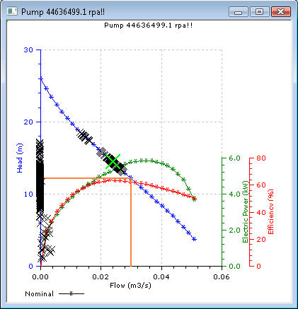
Mechanical power values are also defined in the Head Discharge Table allowing the calculation of an efficiency curve and electric power curve that can be viewed on a graph when analysing pump operation (see below).
Analysing Pump Operation
The operation of a rotodynamic pump can be analysed by graphing the curve for the pump including display of all the operating points for the pump during the simulation.
To display a graph of pump operation:
- Open simulation results in a GeoPlan Window
- Click on the pump to be analysed using the Pick
Graph
 tool. The Pump Graph Dialog will be displayed.
 - Select the Pump operation option from the Pump Graph Dialog. A graph of pump operation will be displayed.

Pump Operation Graph
Modelling Advice
The head across the pump includes the difference between the wet level in the wet well and the water level at the top of the rising main (H). It also includes any friction losses in the rising main itself (DH). This is demonstrated in the diagram below.

Pump Head
H is the head difference between water levels
DH is the friction loss in the rising main itself
It is necessary to include rising mains in the representation of rotodynamic pumps and to model the velocities in them accurately.
Rising Mains
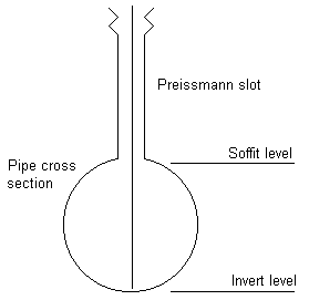
By default, conduits include a Preissmann Slot.
The Preissmann Slot increases the cross sectional area of the pipe when
it is in surcharge. In most surcharged conditions this is not significant,
however in rising mains, where surcharge levels can be large, it can have
an effect on the predicted velocity and hence the friction losses. ![]() Show me
Show me
In rising mains we recommend that the Preissmann Slot is removed. Do this by setting the Solution Model field for the rising main to Pressure. The field can be changed on the Conduit Grid Window of the Links Grid or in the Definition section of the Conduit Property Sheet.
Specifying a Pressure solution model also removes the Base Flow Factor, which would normally be applied to all pipes from the Simulation Parameters.
The Pressure solution model is only implemented whilst the pipe is in surcharge. If the pipe drops out of surcharge, the pipe reverts to the Full solution model for the remainder of the simulation. A warning is given in the results log file.
The most common reason for the pressurised pipe model not to be implemented is that the rising main is not full at the start of the simulation. In other words it has not filled up during initialisation. This may be because no flows pass through the pump during initialisation.
To remedy this, apply a small Base Flow to the subcatchment draining to the upstream (physically lower) end of the rising main. This will cause the rising main to fill up during initialisation, as the water cannot flow back through the pump.

Rotodynamic Pump Schematic View
Note that Base Flow applied to a subcatchment is completely different from the Base Flow Factor applied to all pipes from the Simulation Parameters.
Another reason the pressurised pipe model may not be implemented is if the top of the rising main is not completely full, as shown in the diagram below left.
This is solved by ensuring that the invert level of the downstream gravity pipe is above the soffit level of the rising main. See the diagram below right.


