Snyder Unit Hydrograph Model
The Snyder unit routing model uses the Snyder unit hydrograph method documented in the FHWA-NHI-02-001 HDS2 Highway Hydrology Technical Report.
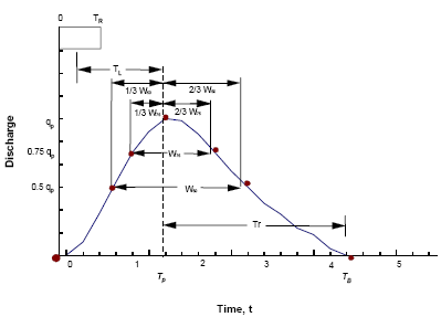
The following parameters are required in order to define the Snyder unit hydrograph:
- TL - lag time
- TR - unit hydrograph duration
- qp - peak discharge
- W50 - hydrograph time width at 50 percent of peak discharge
- W75 - hydrograph time width at 75 percent of peak discharge
Lag Time, TL and Peaking Coefficient, Cp (used to calculate peak discharge) are specified in the Subcatchment Grid Window of the Subcatchments Grid or on the Subcatchment Property Sheet. The Unit Hydrograph Definition for the subcatchment must be set to Snyder.
Seven coordinates can be determined from the above parameters and the hydrograph drawn through these coordinates. (The Equations section below details the calculations for each parameter.)

Snyder Unit Hydrograph Definition (diagram taken from FHWA-NHI-02-001)
In order to construct the unit hydrograpyh, InfoWorks ICM calculates approximate coordinates as detailed in the table below. The calculated base time is then adjusted until the area under the unit hydrograph is equal to 1mm.
Equations
The equations listed in this section are documented in the FHWA-NHI-02-001 HDS2 Highway Hydrology Technical Report. See the report for more details and a worked example.
Lag Time, TL
The value for lag time is provided by the user in the Unit Hydrograph Routing Definition section on the Subcatchment Property Sheet.
Lag time is the time from the centroid of excess rainfall to the hydrograph peak and can be estimated using the following formula:
Where: TL is lag time in hours Ct is lag time coefficient for subcatchment L is length along main channel from outlet to divide, km (mi) Lca is length along main channel from outlet to a point opposite the subcatchment centroid km (mi) a is conversion constant (0.75 for SI units and 1.00 for CU units) |
Unit Duration
Unit duration of excess rainfall is calculated as:
Where: TR is unit duration of excess rainfall, h Lag time can be adjusted for more convenient values of unit duration:
Where: TL(adj) is adjusted lag time for new duration, h TL is original calculated lag time, h TR is original calculated unit duration, h TR' is desired unit duration, h |
Peak Discharge
The peak discharge is calculated by:
Where: qp is unit peak discharge, m3/s/mm (ft3/s/in) Cp is peaking coefficient A is subcatchment area, km2 (mi2) a is conversion constant (0.275 for SI units, 640 for CU units) Peaking coefficient Cp is provided by the user in the Unit Hydrograph Routing Definition section of the Subcatchment Property Window and should be given a value between 0.4 and 0.94. |
Time Base
The time base of the unit hydrograph is calculated by:
Where: TB is time of synthetic hydrograph, days This equation is reasonable for larger subcatchments. For smaller subcatchments it is more reasonable to calculate TB as 3 to 5 times the time to peak. |
W50 and W75
The time widths of the unit hydrograph at 50 percent of peak discharge and 75 percent of peak discharge are calculated by:
Where: W50 is time interval between the rising and falling limbs at 50% of peak discharge, h W75 is time interval between the rising and falling limbs at 75% of peak discharge, h qp is unit peak discharge, m3/s/mm (ft3/s/in) A is subcatchment area, km2 (mi2) a25 is conversion constant (0.18 for SI units, 735 for CU units) a75 is conversion constant (0.10 for SI units, 434 for CU units) |


