Unit Hydrograph Model
A Unit Hydrograph for the subcatchment is determined from user defined parameters, or from parameters calculated by built in methods. The Unit Hydrograph is then used to calculate runoff resulting from the subcatchment net rainfall.
The Unit Hydrograph parameters are specified in the Subcatchment Grid Window of the Subcatchments Grid or in the Unit Hydrograph Routing Definiton section of the Subcatchment Property Sheet.
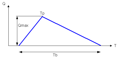
The following data is required in order to define the Unit Hydrograph:
- Tp - time of peak flow
- Tb - total runoff time
- Qmax - maximum flow

Tp and Tb can be defined individually for each subcatchment. Alternatively, Tc, the time of concentration can be used to compute Tp and Tb. The time of concentration is the longest time required for a particle to travel from the watershed divide to the watershed outlet.
The method of calculation is selected from the Unit Hydrograph Definition field of the Subcatchment. The available methods are:
- User-defined Tp and Tb - enter Time to Peak and Base Time values for Subcatchment
- User-defined Tc - enter Time of Concentration value for Subcatchment
- Tc calculated (see Time of Concentration Equations below)
For unit hydrograph definitions except Rational, if Tc is defined or calculated, Tp and Tb are calculated as follows:
|
|
Where: Tp is the time of peak flow Tc is the time of concentration, or the subcatchment response time
fts is the timestep factor ftp is the time to peak factor (The timestep factor and the time to peak factor are user-defined variables and depend on the method chosen for defining Tp from Tc, except for the SCS-User-Tc hydrograph, where fts is set to zero and ftp is set to 2/3.)
Total runoff time, Tb, is calculated from Tp.
For unit hydrograph definitions except SCS-User-Tc:
For unit hydrograph SCS-User-Tc:
Qmax is then calculated via simple geometry:
|
For Rational unit hydrograph:
|
|
|
Time of Concentration Equations
The following methods can be used to calculate Time of Concentration, Tc:
The method to be used is defined in the Unit Hydrograph Definition field of the Subcatchment.
|
|
Where: Tc is time of concentration in minutes TL is lag time in minutes S is subcatchment surface area in hectares p is subcatchment slope % C is runoff coefficient (dimensionless)
C is calculated as:
Where: IMP is proportion of subcatchment area that is permeable (between 0 and 1) t is production coefficient defined for the 'fixed response' volume model if it is chosen |
The Rational method is used as a standard routing model in Japan. See the Japanese Runoff Methodology technical paper for further information.
The method for calculating time of concentration is selected from the Time of concentration method field:
- User - time of concentration, tc is user defined
- Kraven - time of concentration calculated using the Kraven method
- Uniform - time of concentration calculated using the Uniform flow velocity method
- PWRI - time of concentration calculated using PWRI method
|
|
Where: Tc is time of concentration in minutes t1 is travel time of overland flow in minutes t2 is travel time of channel flow in minutes
For catchment areas below 2km2, t2 is assumed to be zero, t1 is calculated as:
Where: t is travel time in minutes A is total area of catchment in km
For catchment areas equal to or greater than 2km2, t2 is calculated as:
Where: L is catchment Dimension in metres W is flood wave celerity in m/s |
|
|
Where: Tc is time of concentration in minutes t1 is travel time of overland flow in minutes t2 is travel time of channel flow in minutes
For catchment areas below 2km2, t2 is assumed to be zero, t1 is calculated as:
Where: t is travel time in minutes A is total area of catchment in km
For catchment areas equal to or greater than 2km2, t2 is calculated as:
Where: L is catchment Dimension in metres W is flood wave celerity in m/s calculated as:
Where: n is equivalent Manning's n R is hydraulic radius in metres I is catchment slope in m/m |
|
|
Where: CPWRI is PWRI coefficient L is catchment dimension in metres S is catchment slope in m/m |


