Weirs (InfoWorks)
Weirs are used for overflow structures and for outlets to storage ponds. Weir controls have the same characteristics for flow in both directions.
A weir is represented as a link of zero length, forming a head-discharge relationship between two nodes. The boundary condition between the link and a node is that of equal water levels. The weir crest invert level determines when the control first comes into operation.
The weir types available in InfoWorks ICM are:
- Standard Weir (Rectangular Full Width Weir) (WEIR) - thin plate weir that extends the full width of the channel
- Variable Crest Weir (VCWEIR) - a standard thin plate weir whose crest level can vary according to a set of control rules. Used for Real Time Control simulations only
- Variable Width Weir (VWWEIR) - a standard thin plate weir whose width can vary according to a set of control rules. Used for Real Time Control simulations only
- Contracted Rectangular Weir (COWEIR) - thin plate weir with a single rectangular notch that does not extend the full width of the channel
- Vee Notch Weir (VNWEIR) - thin plate weir with one or more vee shaped notches
- Trapezoidal Notch Weir (TRWEIR) - thin plate weir with one or more trapezoidal notches
- Broad Crested Weir (BRWEIR) - a weir with a horizontal crest. In practice, the length of the crest is normally equal to the channel width
- Gated Weir (GTWEIR) - a gated weir where the crest level can vary according to a set of control rules. Used for Real Time Control simulations only
Flow Characteristics
The discharge over the various kinds of weir is calculated using the equations below.
There are two flow conditions that are possible over weirs:
- Free discharge: the downstream depth does not affect the upstream depth or discharge. This occurs when the downstream depth is below the crest level.
- Drowned discharge: the downstream depth affects the upstream depth and the discharge. This occurs when the downstream depth is above the crest level.
Standard Thin Plate Weir
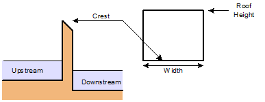
For free discharge InfoWorks ICM uses the governing model equation based on the Kindsvater and Carter equation:
|
|
where: Qo is the free outfall discharge Cd is the discharge coefficient g is the acceleration due to gravity B is the width of the weir Du is the upstream depth with respect to the crest |
For drowned discharge InfoWorks ICM uses the Kindsvater and Carter equation where Dd is greater than zero:
|
|
where: Dd is the downstream depth with respect to the crest |
See BS3680 (Part 4A) for more information.
If the Use Villemonte equation option has been chosen as a Simulation Parameter, when the weir is under drowned conditions, the Villemonte formula is used to modify the free outfall discharge as presented in the equation below:
|
|
where: Q is the discharge Qo is the free outfall discharge (calculated using the free discharge equation above) Dd is the downstream depth with respect to the crest Du is the upstream depth with respect to the crest |
If the water level exceeds the roof height then InfoWorks ICM will use the lower of the flow values calculated by using the weir equations above and the orifice formula.
Contracted Thin Plate Weir
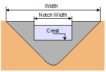
For free discharge InfoWorks ICM uses the Kindsvater and Carter equation, in which a minimum value of critical depth over the weir crest is enforced, and the contracted width is assumed to extend up to the channel wall height.
|
|
where: Qo is the free outfall discharge Du is the upstream depth with respect to the crest p is the height of the weir crest above the channel invert B is the weir width g is the acceleration due to gravity |
For drowned discharge InfoWorks ICM uses the Kindsvater and Carter equation where Dd is greater than zero:
|
|
where: Dd is the downstream depth with respect to the crest |
The Villemonte formula is then used to modify the free outfall discharge. See Equation 3 above.
Trapezoidal Notch Thin Plate (Cipolletti) Weir
Under free discharge, InfoWorks ICM uses the equation:
|
|
where: Qo is the free outfall discharge B is the weir width at crest level Du is the upstream depth with respect to the crest |
The crest is the level at which the weir comes into operation - in other words the base of the trapezoidal notch(es).
The weir is assumed to be drowned if the downstream water level exceeds the crest level. The Villemonte formula is then used to modify the free outfall discharge. See Equation 3 above.
See BS3680 (Part 4A) for more information.
V-Notch Thin Plate Weir
Under free discharge InfoWorks ICM uses the Kindsvater and Shen formula:
|
|
where: Qo is the free outfall discharge g is the acceleration due to gravity Cd is the discharge coefficient. In InfoWorks ICM, this value is fixed at 0.585. This is correct for 90° notch weirs. q is the angle of the notch Du is the upstream depth with respect to the crest |
The weir is assumed to be drowned if the downstream water level exceeds the crest level. The Villemonte formula is then used to modify the free outfall discharge. See Equation 3 above.
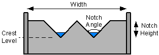
See BS3680 (Part 4A) for more information.
Broad Crested Weir
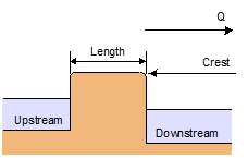
InfoWorks ICM uses the standard formula for a round nosed broad crested weir:
|
|
where: Qo is the free outfall discharge Cd is the discharge coefficient. This is calculated using the formula below Cv is a dimensionless coefficient allowing for the effect of approach velocity B is the width of the weir crest g is the acceleration due to gravity Du is the upstream depth with respect to the crest |
Cd is calculated using the equation:
|
|
where: L is the length of the horizontal section of the crest in the direction of flow |
Cv is then calculated in terms of Cdusing:
|
|
where: A is the cross sectional area of the approach channel below the water level |
When the modular ratio (the ratio above the crest level of downstream depth to calculated upstream depth) exceeds 66% the weir is deemed to be drowned and a nominal headloss is set.

Remember that most controls in a InfoWorks ICM network are treated as operating in the same way hydraulically for flow in both directions. This behaviour is not appropriate for a broad crested weir, which should only have flow in one direction. It is up to you to avoid situations where reverse flow occurs at broad crested weirs in your network.
See BS3680 (Part 4F) for more information.
Gated Weir
Three flow regimes can be used to model for flow over a gated weir:
- when the gate is lowered and the weir operates as a flume or broad crested weir with critical depth in the body of the structure.
- when the gate is raised and critical depth occurs at the gate crest.
- when the direction of flow is from the free crest towards the hinge when performance is similar to a weir with a triangular profile.
These are shown on the diagrams below:
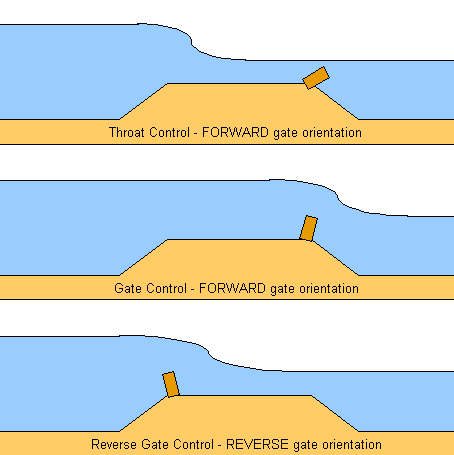
Equations
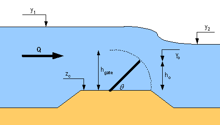
Gated Weir Parameters
If the level on both sides is below the gate crest, then the following equation is used:
|
Equation |
Q = 0 |
Determination of throat/gate and free/drowned flow combinations
m = Modular Limit
b = Breadth of sluice at control section (normal to the flow)
Ctc = Discharge coefficient for throat control
Cgt = Discharge coefficient for gate control
Crev = Discharge coefficient for reverse gate control
|
|
Flow is determined to be throat flow if |Qthroat| < |Qgate| and gate flow otherwise. Throat Flow:
Gate flow:
To determine whether flow is free flow or drowned flow:
|
Forward flow combinations
Free weir flow - throat control
|
Condition |
|
|
Equation |
as Equation (1) |
Drowned weir flow - throat control
|
Condition |
|
|
Equation |
as Equation (1) |
Free weir flow - gate control
|
Condition |
|
|
Equation |
as Equation (2) |
Drowned weir flow - gate control
|
Condition |
|
|
Equation |
As Equation (2) |
Free weir flow - reverse gate control
|
Condition |
|
||
|
Equation |
If q < 22
otherwise
where:
|
Drowned weir flow - reverse gate control
|
Condition |
|
||
|
Equation |
where all terms above are the same as defined for 'Free weir flow - reverse gate control', except fgate, which is as defined in equation (2) |
Reverse flow combinations
The equations and conditions are the same as for the forward flow combinations (described above) but with reverse flow (Q<0). Note that the orientation of the gate specified for reverse flow combinations is relative to the crest, not the flow direction, e.g. for 'Free weir flow - reverse gate, throat control, reverse flow', the position of the gate is not physically oriented the same as for 'Free weir flow - throat control'. For 'Free weir flow - throat control' and 'Free weir flow - forward gate control, reverse flow', the gates are in the same position, relative to the crest.
- Free weir flow - reverse gate, throat control, reverse flow
- Drowned weir flow - reverse gate, throat control, reverse flow
- Free weir flow - reverse gate control, reverse flow
- Drowned weir flow - reverse gate control, reverse flow
- Free weir flow - forward gate control, reverse flow
- Drowned weir flow - forward gate control, reverse flow
The equations used for the gated weir were derived from a physical model. The work is described in HR Wallingford Hydraulic Studies Report EX1296.


