Weir Data Fields (InfoWorks)
Weirs are used for overflow structures and for outlets to storage ponds.
Weir controls have the same characteristics for both flow directions.
To view and edit all weir data, use the Property Sheet.
This table describes all the weir specific data which can be used to define a weir. For details of results fields, see the Link Results Data Fields topic.
 Common Data Fields
 Fields that are common to the majority of objects can be found in the Common Fields topic.
Weir Data
Database Table Name: hw_weir
|
Field Name |
Help Text |
Database Field |
Size |
Precision |
Default |
Error Lower Limit |
Error Upper Limit |
Warning Lower Limit |
Warning Upper Limit |
|||||||||||||||||||||||||||||
|---|---|---|---|---|---|---|---|---|---|---|---|---|---|---|---|---|---|---|---|---|---|---|---|---|---|---|---|---|---|---|---|---|---|---|---|---|---|---|
|
US Node ID |
Type in a node reference or choose an existing node reference from the drop down list. This makes up the first part of the link reference. |
us_node_id |
Text |
64 |
|
0 |
|
|
|
|
|
|||||||||||||||||||||||||||
|
DS Node ID |
Type in a node reference, or choose an existing node reference from the drop down list. |
ds_node_id |
Text |
64 |
|
0 |
|
|
|
|
|
|||||||||||||||||||||||||||
|
Link suffix |
A single character between A and Z or 0 and 9 which completes the link reference. This allows a node to have up to 36 downstream links. The suffix is automatically allocated by the software. |
link_suffix |
Text |
1 |
|
0 |
1 |
|
|
|
|
|||||||||||||||||||||||||||
|
Link type |
The sub-type for this weir. Select from the dropdown list.
|
link_type |
Text |
6 |
|
0 |
WEIR |
|
|
|
|
|||||||||||||||||||||||||||
|
System type |
Choose the System Type from the dropdown list. See System Type for more information.
|
system_type |
Text |
10 |
|
0 |
Other |
|
|
|
|
|||||||||||||||||||||||||||
|
Asset ID |
For reference only. Designed as a reference to an asset database, but could be used for anything. |
asset_id |
Text |
64 |
|
0 |
|
|
|
|
|
|||||||||||||||||||||||||||
|
Sewer reference |
An optional reference to identify the sewer of which this conduit is a part. |
sewer_reference |
Text |
80 |
|
0 |
|
|
|
|
|
|||||||||||||||||||||||||||
|
Branch ID |
Numeric field used to identify to which long section the link is associated. Can be set manually or automatically (see Defining Branches topic for more information). |
branch_id |
Long Integer |
|
|
0 |
|
0 |
|
|
|
|||||||||||||||||||||||||||
|
InfoAsset unique ID |
Unique ID associated with the corresponding object in an InfoAsset Manager database. When importing from InfoAsset Manager, the InfoAsset ID can be copied from the InfoAsset database in order to maintain links between the two networks. |
asset_uid |
GUID |
|
|
0 |
|
0 |
0 |
0 |
0 |
|||||||||||||||||||||||||||
| InfoAsset ID |
Used to store the ID of the corresponding InfoAsset object when Importing from a Collection Network. |
infonet_id | Text | 40 | 0 | |||||||||||||||||||||||||||||||||
|
DS settlement efficiency (%) |
See Upstream Settlement Efficiency. |
ds_settlement_eff |
Long Integer |
|
|
0 |
0 |
0 |
100 |
|
|
|||||||||||||||||||||||||||
|
US settlement efficiency (%) |
The Settlement Efficiency fields allow you to set the effectiveness of an overflow for trapping out sediment. The overflow is a link (normally a pipe) attached to a node acting as a storage tank (storage node or manhole). Normally the upstream end of the link will be attached to the node and act as the overflow. The Upstream Settlement Efficiency determines the efficiency for the overflow. In some circumstances the link may be reversed (storage tank at the downstream end) and the Downstream Settlement Efficiency will be used. In many cases an overflow will attach to an outfall from the system. It would be very unusual to have both Upstream Settlement Efficiency and Downstream Settlement Efficiency set to non-zero values. The valid range is 0-100%. 0% means the overflow acts as a normal continuation link. 100% means that the overflow traps out as much sediment as possible. |
us_settlement_eff |
Long Integer |
|
|
0 |
0 |
0 |
100 |
|
|
|||||||||||||||||||||||||||
|
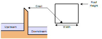
Crest |
The level at which the weir first comes into operation. For vee and trapezoidal notch weirs, and contracted rectangular weirs, this is the height of the base of the notch. For a gated weir this is the height of the sill. InfoWorks ICM uses this as the initial value for a Variable Crest Weir or a gated weir unless overridden by the data entered on the Regulator Page.
|
crest |
Double |
|
Z |
3 |
|
-9999 |
9999 |
|
6000 |
|||||||||||||||||||||||||||
|
Width |
The width of the rectangular weir. InfoWorks ICM uses this value as the initial value for a Gated Weir or a Variable Width Weir unless overridden by the data entered on the Regulator Page. |
width |
Double |
|
L |
3 |
|
0 |
|
|
|
|||||||||||||||||||||||||||
|
Roof height |
Roof Height for the weir (optional, more for pipes than open channel). If you enter a value here, the weir behaves as a sluice gate when the water level is above the roof height. If you do not give a value here, it is assumed that the weir does not have a roof. Applies only to WEIR, VCWEIR, and VWWEIR types of weir. |
height |
Double |
|
L |
3 |
|
0 |
|
|
|
|||||||||||||||||||||||||||
|
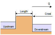
Length |
The distance across the flat part of the top of the weir measured parallel to the direction of flow. The distance does not include the round noses of the weir Broad Crested Weir only.
|
length |
Double |
|
L |
3 |
|
0 |
|
|
|
|||||||||||||||||||||||||||
|
Discharge coefficient |
The coefficient for the weir flow equations. A default value of 0.85 corresponds to a weir of width equal to that of the approach channel for the Standard Rectangular Weir types WEIR, VCWEIR and VWWEIR only. Values typically range between 0.2 and 3.0. For gated weirs (GTWEIR), a default of 1 is used. |
discharge_coeff |
Double |
|
|
2 |
0.01 |
|
|
|
||||||||||||||||||||||||||||
|
Secondary discharge coefficient |
This applies when the depth of water is greater than the roof or gate height, and orifice/sluice gate equations apply. The default is either the primary discharge coefficient (for Standard Rectangular Weir types WEIR, VCWEIR or VWWEIR) or 1 for gated weirs (GTWEIR). |
secondary_discharge_coeff |
Double |
|
|
2 |
0.01 |
|
|
|
||||||||||||||||||||||||||||
| Reverse discharge coefficient | Discharge coefficient for reverse gate for a gated weir (GTWEIR). The default is 1. |
reverse_gate_discharge_coeff | Double | 2 | 0.01 | |||||||||||||||||||||||||||||||||
|
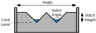
Notch height |
The vertical distance from the base (apex) of the notch to the top of the weir plate. Vee and Trapezoidal Notch Weirs only. |
notch_height |
Double |
|
L |
3 |
|
0.06 |
|
|
|
|||||||||||||||||||||||||||
|
Notch angle |
The angle at the base (apex) of the notch in degrees. This means the full angle, not the angle of side slope. Vee Notch Weir only. Note: This angle is calculated automatically when importing data from SWMM5. |
notch_angle |
Double |
|
ANGLE |
2 |
90 |
20 |
100 |
|
|
|||||||||||||||||||||||||||
|
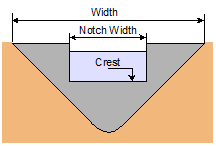
Notch width |
For Contracted Rectangular Weirs, this is the width of the single notch. For Trapezoidal Notch Weirs this is the width of the base of one notch. The weir may have more than one notch. The side slope of all notches is assumed to be 14 degrees. Contracted Rectangular and Trapezoidal Notch Weirs only.
|
notch_width |
Double |
|
L |
3 |
|
0.000001 |
|
|
|
|||||||||||||||||||||||||||
|
Number Of notches |
You can have more than one vee or trapezoidal shaped notch in a weir. Enter the number here. All the notches are identical. Vee and Trapezoidal Notch Weirs only. |
number_of_notches |
Long Integer |
|
|
0 |
1 |
1 |
|
|
|
|||||||||||||||||||||||||||
| Modular limit | Modular limit for a gated weir. | modular_limit | Double | 3 | 0.7 | 0.01 | 1 | |||||||||||||||||||||||||||||||
| Gate height | The height of gate (dimension from bottom to top of gate). | gate_height | Double | L | 3 | 0 | ||||||||||||||||||||||||||||||||
| Orientation | The direction of the gate can be set to Forward or Reverse. | orientation | Text | 8 | 0 | FORWARD | ||||||||||||||||||||||||||||||||
| Minimum opening | The minimum opening height for a gated weir. This value must not exceed the specified Gate height. | minimum_opening | Double | L | 3 | 0 | 0 | |||||||||||||||||||||||||||||||
| Maximum opening | The maximum opening height for a gated weir. | maximum_opening | Double | L | 3 | |||||||||||||||||||||||||||||||||
| Initial opening | The initial opening height for the gated weir. | initial_opening | Double | L | 3 | 0 | 0 | |||||||||||||||||||||||||||||||
|
Minimum width |
The minimum width for a variable weir. Applies to a variable width weir (VWWEIR) or, if the Minimum crest field is not set, then this parameter will also apply to variable crest level weir (VCWEIR). |
minimum_width |
Double |
|
L |
3 |
|
|
|
|
|
|||||||||||||||||||||||||||
|
Maximum width |
The maximum width for a variable weir. Applies to a variable width weir (VWWEIR) or, if the Maximum crest field is not set, then this parameter will also apply to variable crest level weir (VCWEIR). |
maximum_width |
Double |
|
L |
3 |
999 |
|
|
|
|
|||||||||||||||||||||||||||
|
Minimum crest |
The minimum elevation for a variable crest level weir. If not set, the specified Minimum width will be used instead. |
minimum_elevation |
Double |
|
Z |
3 |
|
|
|
|
|
|||||||||||||||||||||||||||
|
Maximum crest |
The maximum elevation for a variable crest level weir. If not set, the specified Maximum width will be used instead. |
maximum_elevation |
Double |
|
Z |
3 |
999 |
|
|
|
|
|||||||||||||||||||||||||||
|
Positive change |
The rate at which the width increases or the crest rises. The value must be greater than zero. |
positive_speed |
Double |
|
DY |
5 |
|
0.000001 |
|
|
|
|||||||||||||||||||||||||||
|
Negative change |
The rate at which the width decreases or the crest falls. The value must be greater than zero. |
negative_speed |
Double |
|
DY |
5 |
|
0.000001 |
|
|
|
|||||||||||||||||||||||||||
|
Threshold |
The minimum change in width (VWWEIR) or crest level (VCWEIR and GTWEIR) that the software will implement. Any smaller change will be ignored. This prevents oscillation. |
threshold |
Double |
|
L |
3 |
0 |
0 |
|
|
|
|||||||||||||||||||||||||||
|
Points |
This field defines the geometry of the link. The underlying data consists of a series of (x,y) pairs defining the vertices of the link. Each link is made up of a series of straight lines between the defined (x,y) points. This data is not displayed on the grid or property sheet.  Link Vertice Export Link Vertice Export
Link vertices are included when you export link data to CSV files. There are two options available for exporting link vertices. These are selected on the Select CSV Export Options Dialog using the Coordinate Arrays Format dropdown list. The options are:
|
point_array |
Array |
|
XY |
0 |
|
|
|
|
|
 Water Quality