Skeletoniser
The Skeletoniser is used to simplify the network by reducing the number of nodes and links in the model while preserving hydraulic integrity.
The Skeletoniser carries out two basic actions:
- Branch Pruning: Involves removal of pipes that are not significant enough to be included in the model. Pruning can be constrained by a maximum pipe size specified by the user. As each node/link pair is removed, customer points and spatial data items allocated to the removed link are re-allocated to one of the links at the remaining node.
- Joining of similar pipes: Removes nodes between two similar pipes (same diameter, roughness, material, age and local loss coefficient) and joins the pipes. Customer points and spatial data items allocated to the old links are re-allocated to the new link.
In addition to branch pruning and pipe joining, the Skeletoniser View offers a Remove Links facility, which is described later in this topic.
Skeletonisation Method

It is recommended that Skeletonisation is carried out on a newly checked out version of the network.
To carry out a skeletonisation:
- Open the network to be simplified.
- Open a control data set (optional). The skeletonisation options available are enhanced if control data is associated with the network.
- Choose Skeletoniser from the Tools menu. This displays the Skeletoniser View.
- Create a selection to be skeletonised either by:
- highlighting a selection on the GeoPlan and then using the Current button
- browsing for a selection set using the ... button
- dragging a selection list into the Selection List box
- Define links to be considered for skeletonisation using the Skeletoniser Options dialog from the Skeletoniser View.
- Use the Skeletonise button to run a skeletonisation.
The skeletoniser uses the following process to simplify the network:
Step 1
Step 1 of the skeletonisation process is as follows:
- Check for nodes in the network completely surrounded by links to be considered for skeletonisation as defined by the selection list in the Skeletoniser View and the options set in the Skeletoniser Options dialog. Mark these nodes as 'interior'.
- If the from-node and to-node of a link to be considered for skeletonisation is marked as "interior", remove the link and re-allocate any demand to another suitable node.
Step 2
Step 2 is an iterative process; the software will continue to perform these steps until none of the options are true:
- For each node to be considered for removal, count all of the links attached to the node that are available for skeletonisation. Find the largest diameter among these links.
- If there are just two available links, there are two possibilities:
- Remove the node and join the two links together
- Can a simple loop be identified? Trace a chain of links until exactly two available links are found; if the starting point is reached then remove one of the links around the node.
- If there is just one link then the pipe will be removed and the demand will be moved to a suitable node.
- If there are parallel pipes (shared US/DS node), remove one of the pipes and move the demand to the second.
For pruned branches, objects will be generated in the Pruned Link Table to represent the geometry of the links that have been removed. Pruned links are displayed as a separate layer in the GeoPlan.

The skeletonisation process will stop at valve and pump objects. To include these objects for simplification it is necessary to convert them into pipe objects (export the objects to a CSV and then use the Open Data Import Centre to import them as pipes).
Link Removal
This facility removes selected links and moves allocated demand to adjacent nodes. This tool can be used to remove user selected links that will not be removed by skeletonisation, for example, to remove subnetworks of small diameter pipes that would not be removed by skeletonisation due to interconnections between loops.
The Link Removal tool follows the same process as the skeletoniser tool (described above), however, valve and pump objects are included when carrying out link removal.

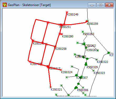
Example of a case where Link Removal may be used
Pruned Objects
The pruned links are displayed in the GeoPlan Window as a line with no nodes. By default this line is coloured grey. The display options for pruned links can be changed by using the Display Page on the GeoPlan Property Sheet.
You can view the properties of a pruned section of the network in the
same way as any other network object. Select the tool
 and then click the pruned object on the GeoPlan Window. This displays the Pruned
Objects Properties dialog. The dialog contains the node and link names
of all objects pruned in a Skeletonisation run.
Note that the group of pruned objects in a Skeletonisation run are given an automatically generated name of the form {39784191-6317-4510-973E-B941C0811C3B}. This is called a GUIDA Globally Unique IDentifier, or GUID, is an automatically generated identifier that is guaranteed to be unique across all systems. It is generated using a complex algorithm based on the date and time and the individual computer's network card ID. GUIDs take the form {629810C2-3F6B-11D3-9BF3-00600891B690} and you will see them in a number of places where uniqueness is essential., or Globally Unique IDentifier.
Whilst the Skeletoniser View remains open, skeletonisation changes made to the network can be undone, provided that the Enable Undo option on the Skeletoniser View has been checked. Once the Skeletoniser View is closed, changes made due to skeletonisation prior to the view being closed, cannot be undone.
