Valve Control page
InfoWorks WS Pro allows for the following types of control valve:
- Flow Controlled Valve (FCV): operates according to the variations of flow in a control pipe
- Flow Modulated Valve (FMV): controls pressure in a control valve according to variation of flow through valve
- Flow Regulating Valve (FRV): operates to a target flow profile
- Open/Closed (OCV): opening of valve controlled according to pressure at a control node
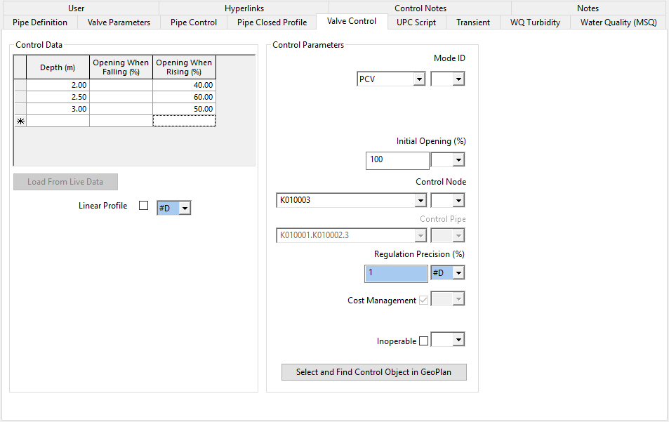
- Pressure Controlled Valve (PCV): operates according to pressure variations at a control node (or water level changes in a control reservoir)
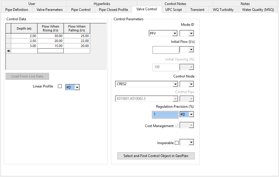
- Pressure/Flow Valve (PFV): operates according to pressure/depth monitored at a control node/reservoir
- Pressure Reducing Valve (PRV): reduces pressure at a downstream control node to a given constant or time-varying level
- Pressure Reducing / Sustaining Valve (PRSV): attempts to reduce pressure at a downstream reducing control node and maintain a minimum pressure at an upstream sustaining control node to a given constant or time-varying level
- Pressure Sustaining Valve (PSV): maintains a minimum pressure at an upstream control node to a given constant or time-varying level
- Time Controlled Valve (TCV): operates according to a time schedule
- Throttled Valve (THV): acts as an additional loss of pressure, thus reducing through-flow
Notes:
- Valve types FRV, PRV, PSV, and TCV can be given control profiles by loading from a live data source.
- If a valve is not given a control policy, InfoWorks WS Pro will assume that it is open throughout the simulation.
- Gate valves may be used as isolation valves (on/off control). However, it is recommended that, in general, gate valves are not used as control valves.
- For more general information on controls, see About controls (control data).
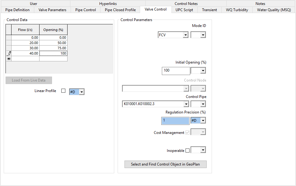
The flow controlled valve (FCV) reacts according to changes of flow in a control pipe specified by the user.
Flow controlled valves are sophisticated devices and are comparatively rare in practice; yet offer considerable scope for the fine control of distribution systems. When there is an exceptional demand, for example from fire fighting, the valve could open up fully. If the demand increases further, perhaps due to a burst , it will shut down automatically.
The user specifies the relationship between percentage opening of the valve and flow through the valve. The user also specifies the initial opening of the valve at the start of the simulation. If an initial opening is not entered, InfoWorks WS will assume that the valve is closed throughout the simulation.
By default no interpolation is used between data points. Each value entered in the grid is maintained until the next date / time entry, or until the end of the simulation. Check the Linear Profile box for linear interpolation to be used between data points.
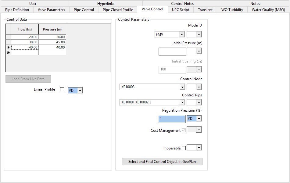
The flow modulated valve (FMV) is used to control the pressure in a control node specified by the user.
The valve uses the measured flow through the valve to control the pressure at the control node, which is normally close to the valve. This valve will often be used to set the pressure at a remote node when the relationship between the pressures at the two nodes is understood from measurements.
This saves the expense of telemetry feedback from the remote node being used to control the valve.
The user specifies the relationship between the pressure to be maintained at the control node and flow through the valve.
By default, no interpolation is used between data points. Each value entered in the grid is maintained until the next date / time entry, or until the end of the simulation. You can check the Linear Profile box for linear interpolation to be used between data points.
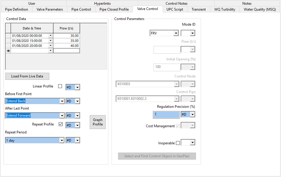
The flow regulating valve (FRV) delivers flow through the valve to a constant target flow or a time variable flow profile specified by the user.
A flow regulating valve may be used for example to regulate transfer of water from one area to another.
The user specifies a constant flow and/or a time varying flow profile to be delivered through the valve.
Note: If both a constant target flow and a series of variable target flows have been entered, the variable target flows are used.
When using a time varying flow profile, by default no interpolation is used between data points. Each value entered in the grid is maintained until the next date / time entry, or until the end of the simulation. You can check the Linear Profile box for linear interpolation to be used between data points.
For details of options available for extending the profile outside of the entered dates / times, see Profile extension options.
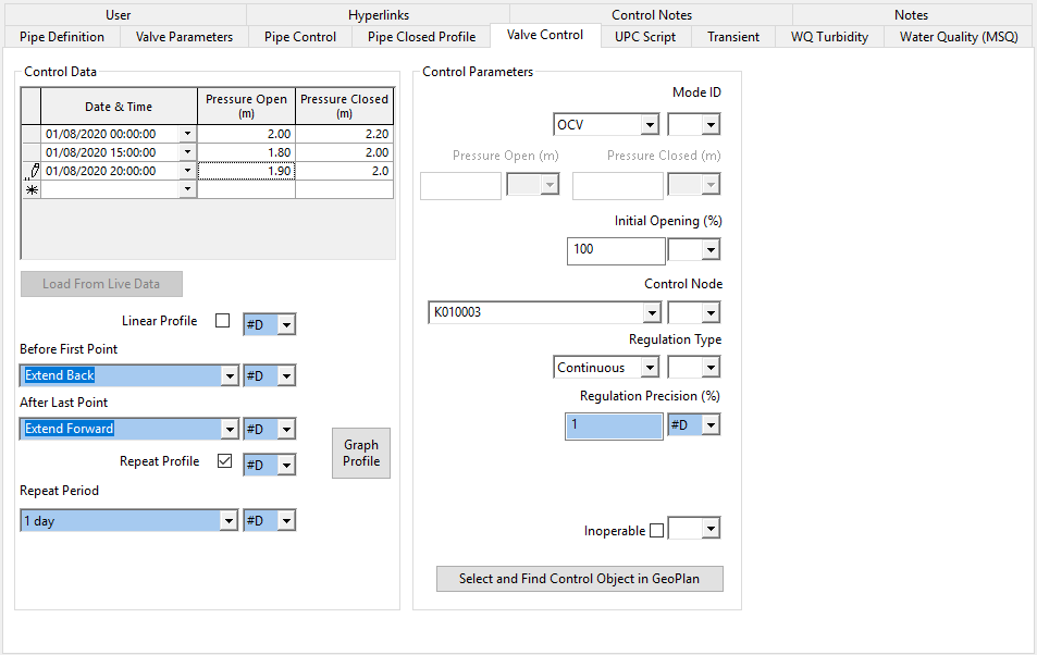
The opening of an open/closed valve (OCV) is controlled by the pressure at a control node. Constant pressure values at which the valve is fully open or fully closed may be specified. Alternatively, a time varying profile of open and closed pressures may be defined.
An open/closed valve may be used for example to maintain varying levels in a reservoir throughout the day.
The user specifies constant pressure open and pressure closed values flow or a time varying profile of pressure open and pressure closed values.
Note: If both constant pressure values and a series of variable pressure values have been entered, the variable pressure values are used.
When using a time varying profile, by default no interpolation is used between data points. Each value entered in the grid is maintained until the next date / time entry, or until the end of the simulation. You can check the Linear Profile box for linear interpolation to be used between data points.
For details of options available for extending the profile outside of the entered dates / times see Profile extension options.
Regulation Type may be set to Continuous or On/Off.
- When set to Continuous, valve opening is determined by using linear interpolation between the current open and closed pressure values.
- When set to On/Off, valve opening is either set to 0% or 100%.
If the Control Node is a reservoir and the reservoir initial depth is out of range of the OCV pressure settings, the valve Initial Opening will be reset if it is not consistent with the initial open and closed pressure values.
The valve operates according to pressure/depth monitored in a control node/reservoir.
This valve can be used to simulate float valve control where measurements have shown the valve to be sticking. Separate opening profiles can be defined for rising and falling levels.
The user specifies the relationship between the control pressure/depth and valve opening.
InfoWorks WS Pro can also simulate quite sophisticated devices like two-way valve, where there are two control curves: one when water level/pressure is increasing, and a different one when water level/pressure is falling.
In simpler cases, the functioning of the valve does not depend on whether level/pressure is rising or falling. To model these cases data should only be entered in the Opening When Rising column, leaving the Opening When Falling column blank.
By default no interpolation is used between data points. Each value entered in the grid is maintained until the next date / time entry, or until the end of the simulation. Check the Linear Profile box for linear interpolation to be used between data points.
The valve operates according to pressure/depth monitored in a control node/reservoir.
This valve could be used to regulate the flow into a reservoir depending on the level in the reservoir and whether it is rising or falling.
The user specifies the relationship between the control pressure/depth and flow through the valve.
Two control curves should be specified: one when water level/pressure is rising, and a different one when water level/pressure is falling.
By default, no interpolation is used between data points. Each value entered in the grid is maintained until the next date / time entry, or until the end of the simulation. You can check the Linear Profile box for linear interpolation to be used between data points.
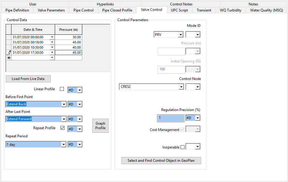
The Pressure Reducing Valve (PRV) reduces pressure in a downstream control node to a preset pressure. This target pressure may be constant or time-varying. It is also possible to specify a constant ratio pressure setting between upstream and downstream pressure.
As upstream pressure increases, the valve will close, creating more headloss until the target pressure is achieved. As upstream pressure decreases the valve will open. If the upstream pressure falls below the target pressure, the valve will open fully.
Pressure reducing valves are often used as a means of reducing leakage in areas that would experience high pressures if not controlled.
The user specifies a downstream pressure and/or a time varying pressure profile to be maintained.
Note: If both a constant target pressure and a series of variable target pressures have been entered, the variable target pressures are used.
If a value between 0 and 1 is entered as the constant target pressure, the valve will be simulated as a constant ratio PRV where:
Downstream Pressure in control node = Pressure value specified * Upstream Pressure
or
Pressure Value specified = Downstream Pressure / Upstream Pressure
When using a time varying pressure profile; by default no interpolation is used between data points. Each value entered in the grid is maintained until the next date / time entry, or until the end of the simulation. You can check the Linear Profile box for linear interpolation to be used between data points.
For details of options available for extending the profile outside of the entered dates / times see Profile extension options.
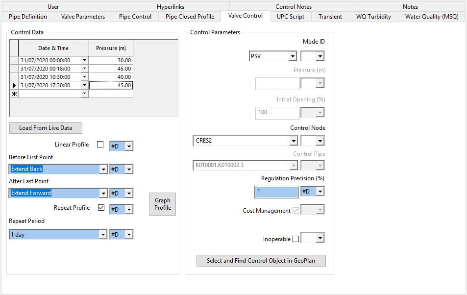
The Pressure Sustaining Valve (PSV) maintains a minimum preset pressure in an upstream control node. This pressure may be constant or time-varying.
As upstream pressure decreases, the valve will close. As upstream pressure increases, the valve will open.
Pressure sustaining valves may be used, for example, in distribution systems with cascading pressure zones, where a downstream zone demand may cause low pressure problems in an upstream zone if not controlled.
The user specifies a minimum upstream pressure or a time varying pressure profile to be maintained.
Note: If both a constant target pressure and a series of variable target pressures have been entered, the variable target pressures are used.
When using a time varying pressure profile, by default no interpolation is used between data points. Each value entered in the grid is maintained until the next date / time entry, or until the end of the simulation. You can check the Linear Profile box for linear interpolation to be used between data points.
For details of options available for extending the profile outside of the entered dates / times see Profile extension options.
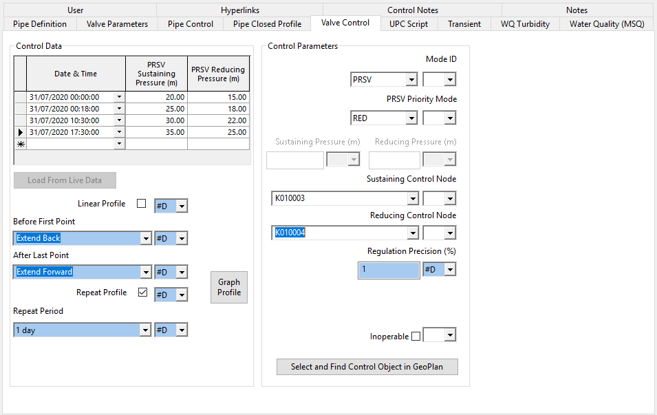
The Pressure Reducing / Sustaining Valve (PRSV) combines the functions of the PRV and PSV.
The valve will attempt to reduce downstream pressure at a reducing control node and sustain upstream pressure at a sustaining control node to specified target pressures.
The PRSV priority mode is used to set which pressure target takes priority:
- In mode SUS the priority is to sustain the upstream pressure target. As long as the upstream target pressure is equalled or exceeded, the valve will also attempt to maintain the downstream pressure.
- In mode RED the priority is to maintain the downstream pressure target. As long as the pressure downstream equals or is below the downstream target pressure, the valve will also attempt to sustain upstream pressure.
The user specifies a minimum upstream pressure and maximum downstream pressure or a time varying pressure profile to be maintained.
Note: If both constant target pressures and a series of variable target pressures have been entered, the variable target pressures are used.
When using a time varying pressure profile, by default no interpolation is used between data points. Each value entered in the grid is maintained until the next date / time entry, or until the end of the simulation. You can check the Linear Profile box for linear interpolation to be used between data points.
For details of options available for extending the profile outside of the entered dates / times see Profile extension options.
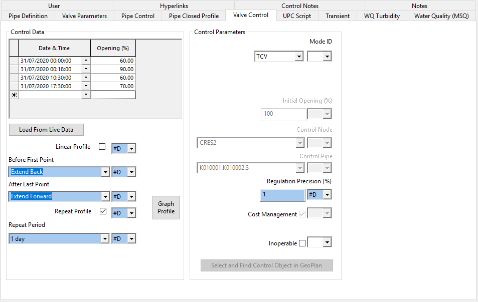
The time controlled valve operates to a time schedule specified by the user.
Time controlled valves may be used for example for scheduled transfer of water from one area to another.
This option is also particularly useful for calibration of models.
The user specifies a time varying profile for valve operation over the simulation time.
By default no interpolation is used between data points. Each value entered in the grid is maintained until the next date / time entry, or until the end of the simulation. You can check the Linear Profile box for linear interpolation to be used between data points.
For details of options available for extending the profile outside of the entered dates / times see Profile extension options.
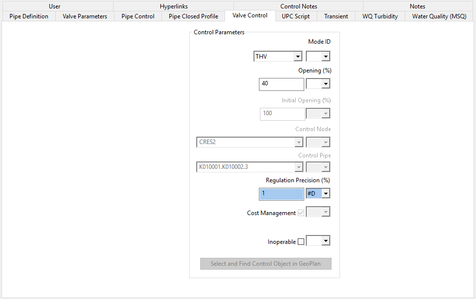
The throttled valve acts as a local obstruction to flow. The opening of the valve remains constant during the simulation.
Throttle valves may be used for example to restrict flow through pumps.
This option may also be used in calibration of models, where a local obstruction in a pipe is suspected.
The user specifies the percentage opening of the valve, which is maintained throughout the simulation.
Profile extension options
The following options are available for extending the profile outside of the entered dates / times for FRV, OCV, PRV, PSV, PRSV and TCV valves:
| Data Field | Description | ||||||
|---|---|---|---|---|---|---|---|
|
Before First Point |
|
||||||
| After Last Point |
|
||||||
|
Repeat Profile (checkbox) |
If checked, repeats a profile (from 00:00 for the selected Repeat Period) for the duration of the simulation. IMPORTANT: When using the Repeat Profile option, if the defined profile spans over the selected Repeat Period, the profile will not be repeated. |
||||||
|
Repeat Period |
Profile period that will be repeated throughout simulation, if the Repeat Profile box is checked. |
