Ancillaries
Ancillaries include channels and flow control structures such as a weir or a pump.
Ancillaries are defined as a link between two nodes. The link is used to join asset (or connection) nodes and reflects the connection and direction of water flow between the nodes. It is not required that the ancillary objects are connected into the asset network and they may be treated as independent assets if this is more convenient.
Ancillaries can be created on the GeoPlan Window or Asset Grid Window. See Digitising Network Objects for details.
Ancillary structures are not defined in quite the same way as pipes. For a pipe, a unique combination of Upstream Node ID, Downstream Node ID and Suffix must be specified. For an ancillary control structure a unique ID must be specified. There can then be more than one structure linking a pair of nodes without need to specify a unique suffix for each one.
The objects can be viewed and edited from the Object Properties Window or from the Asset Grid Window.
The different types of ancillary available are as follows:
A channel object is used to represent an open channel or waterway, whether natural or man made.
See the Channel Data Fields topic for further information.
Flumes are effectively constrictions in a channel or pipe. They are usually used to allow accurate flow measurements to be made.
Flumes in InfoAsset Manager can have one of three cross sections:
- Rectangular - rectangular flumes are simple to construct. They usually need a hump in the middle of the throat to prevent ponding or drawdown if the discharge is above or below the design discharge.
- U-shaped - always with a semi-circular invert (not parabolic, as often used for grit traps). U-shaped flumes are very common in urban drainage, for use with U-shaped channels and circular conduits.
- Trapezoidal - trapezoidal flumes are useful if a wide range of discharges is expected.
A flume that has the same type of cross section as the channels or pipes on either side is normally expected.
See the Flume Data Fields topic for further information.
An orifice plate controls the discharge from a storage tank or pond. It consists of a plate with a hole, usually circular, for the flow to pass through.
See the Orifice Data Fields topic for further information.
Pumps can be used to represent a range of different pump assets.
See the Pump Data Fields topic for further information.
Head discharge tables define the behaviour of some ancillary control objects, such as a pump, by listing the discharge from the control at varying head levels. Mechanical power can also be defined in the table. The values for the mechanical power can be used to analyse the efficiency of, for example, the pump.
Linear interpolation is used between given values. Linear extrapolation is used outside the given range.
See the Head Discharge Table Data Fields topic for further information.
InfoAsset Manager allows sloping bar screens to be included in the network. A screen is used to trap debris in the network, possibly at the entrance to a treatment works.
See the Screen Data Fields topic for further information.
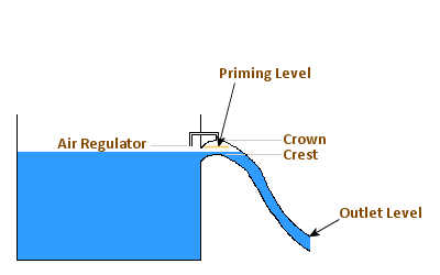
A siphon is an overflow structure that can consist of a single siphon tube or an array of identical siphon tubes. The siphon operates very like a weir structure when the water level is less than or equal to the siphon's Priming Level. Above this level the siphon operates, hydraulically, in a very similar way to an orifice located at the siphon outfall.

Plan view of an Array of Siphons

Siphon Cross Section showing levels
See the Siphon Data Fields topic for further information.
Sluice gates or penstocks are rectangular drop gates and may be used as the outflow control on storage tanks or ponds.
See the Sluice Data Fields topic for further information.
The User Ancillary allows a user defined ancillary structure to be included in the network.
See the User Ancillary Data Fields topic for further information.
Valves can be used to represent a range of different valve type assets.
See the Valve Data Fields topic for further information.
A vortex is a flow control device used to control site discharge rates to a downstream drainage system or water course. For example, a vortex may be used to control flow from stormwater attenuation tanks in order to prevent downstream flooding. The device operates by directing flow to rotate inside a cylindrical vessel.
See the Vortex Data Fields topic for further information.
Weirs can be used to represent a range of different weir type assets.
See the Weir Data Fields topic for further information.
