Graphical Feedback on Custom Labels
Visual feedback about the operating state of some network objects is displayed on Standard Labels.
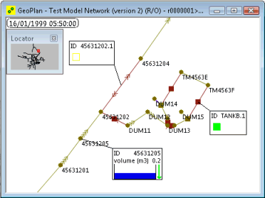
For network objects with relevant controls, a colour coded symbol will be displayed on the label. The colour codes for the symbols follow the general rules:
- Black - Off or No Flow
- Yellow - Operating in intermediate state
- Green - Design Operation
- Red - Extreme Operation
Visual feedback is also available for some parameters; for example, level in a manhole. If these parameters are selected for display on a label a small graphic will be displayed. The graphic is updated during replay of the simulation to give feedback on the state of the network object. Parameters for which visual feedback will be displayed will have the text (Activates graphic) next to the their name on the Custom Label Settings Dialog - Content page.
The following table provides details about the visual feedback available on labels:
|
Network Object |
Symbol/Network Label Graphic |
|||||||||||||||
|---|---|---|---|---|---|---|---|---|---|---|---|---|---|---|---|---|
|
Manhole and Storage Node |
Visual feedback is displayed for the Volume (volume) and Level (depnod) Node parameters. A varying height bar representing the Volume/level at the manhole/storage node is displayed. An arrow shows if the volume/level at the node is currently increasing or decreasing. |
|||||||||||||||
|
Flume |
The colour codes for the Flume object symbol are as follows:
|
|||||||||||||||
|
Orifice |
The colour codes for the Orifice object symbol are as follows:
Visual feedback is displayed for the Regulator State (STATE_Q) Orifice Parameter (Variable Discharge Orifice only). A varying height bar representing the current Limiting Discharge for the Variable Discharge Orifice is displayed. An arrow shows if the limiting discharge is currently increasing or decreasing. |
|||||||||||||||
|
Siphon |
The colour codes for the Siphon object symbol are as follows:
|
|||||||||||||||
|
Sluice |
The colour codes for the Sluice object symbol are as follows:
Visual feedback is displayed for the Regulator State (STATE_L) Sluice Parameter (Variable Sluice Gate only). A varying height bar representing the current opening of the Variable Sluice Gate is displayed. An arrow shows whether the sluice gate opening is currently increasing or decreasing. |
|||||||||||||||
|
Weir |
The colour codes for the Weir object symbol are as follows:
Visual feedback is displayed for the Regulator State (STATE_Z) Weir Parameter (Variable Crest Weir only). A varying height bar representing the current crest level of the Variable Crest Weir is displayed. An arrow shows whether the crest level is currently increasing or decreasing. Visual feedback is displayed for the Regulator State (STATE_W) Weir Parameter (Variable Width Weir only). A varying height bar representing the current width of the Variable Width Weir is displayed. An arrow shows whether the width is currently increasing or decreasing. |
|||||||||||||||
|
Flap Valve Screen User Defined Inlet Culvert Outlet Culvert |
The colour codes for Flap Valve, Screen, User Defined, Inlet Culvert and Outlet Culvert object symbols are as follows:
|
|||||||||||||||
|
Pump |
The colour codes for the Pump object symbol are as follows:
Visual feedback is displayed for the Regulator State (STATE_Q) Pump Parameter (Variable Speed Pump only). A varying height bar representing the current discharge of the Variable Speed Pump is displayed. An arrow shows whether the discharge is increasing or decreasing. |

Graphical Labels example
