Headloss Curves
A headloss condition must be specified at each end of a conduit. The headloss condition represents the extra energy loss due to turbulence at a manhole or junction.
Headloss conditions are specified in the US headloss type and DS headloss type fields for the conduit by selecting a headloss curve. There are a number of built-in headloss curves available; alternatively a user-defined curve may be specified:
- FHWA - headloss is calculated based on the FHWA Inlet and Access Hole Energy Loss method as described in the FHWA HEC 22 Urban Drainage Manual. Appropriate for closed conduits connected to manholes.
- FIXED - headloss is calculated using built-in headloss curve. Appropriate for situations when there is a known headloss, such as entry into a reservoir or an open channel with bends.
- HIGH - headloss is calculated using a built-in headloss curve. Appropriate for badly connected manholes that are benched only to half pipe height.
- NONE - no headloss
- NORMAL - headloss is calculated using a built-in headloss curve. Appropriate for well-constructed manholes on pipe systems, or for small open channel systems.
- User defined - select a user defined Headloss Curve ID
The default headloss condition for an individual conduit is the global value specified in the User Defined Defaults; this has a default value of normal manhole headloss.

In order to use the FHWA headloss condition for networks created in versions of InfoWorks ICM prior to version 3.5, it is necessary to validate the network. Validating the network will update the built-in headloss curves to include the FHWA curve type.
The headloss equation used when using Normal or High headloss types is:
|
|
where: Dh = headloss ku = user defined headloss factor ks = surcharge ratio coefficient kv = velocity coefficient v = flow velocity (m/s) g = acceleration due to gravity (m/s2)
The user defined headloss factor ku is defined in the US/DS headloss coefficient fields of the conduit. The option selected in the US/DS headloss type fields of the conduit determines how ks is calculated. An in-built curve is used to calculate kv. |
There are only two situations in which this equation does not apply:
- where the manhole and pipe immediately downstream of the pipe in question are sufficiently lower so that they are effectively hydraulically independent. In this case the headloss equations do not apply to the downstream end of the pipe and it acts similar to a free outfall.
- where the pipe is empty, as headloss does not apply to the notional baseflow required to achieve numerical stability.
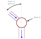
The user defined headloss factor is generally used to represent the fact that the amount of change of flow direction at a manhole affects headloss. The amount of change of direction is described by the angle of approach.
Suggested values of ku for various angles of approach are presented below. If a pipe includes several bends, the values of ku should be summed.

|
|
Inference can be used to automatically apply values of ku to the network.
The surcharge ratio coefficient defines the relationship between headloss and the depth of flow in the pipe:
|
|
where: flow depth = level in the node - invert level of pipe (immediately up or downstream of it) |
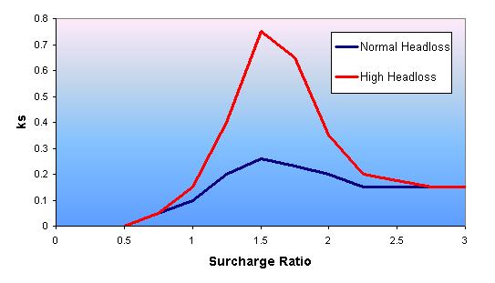
The relationship between surcharge ratio coefficient ks and surcharge ratio is given by built in curves for normal and high headloss types.

| Surcharge ratio | Normal headloss factor | High headloss factor |
|---|---|---|
|
0.50 |
0.001 |
0.001 |
|
0.75 |
0.05 |
0.05 |
|
1.00 |
0.10 |
0.15 |
|
1.25 |
0.20 |
0.40 |
|
1.50 |
0.26 |
0.75 |
|
1.75 |
0.23 |
0.65 |
|
2.00 |
0.20 |
0.35 |
|
2.25 |
0.15 |
0.20 |
|
2.50 |
0.15 |
0.175 |
|
2.75 |
0.15 |
0.15 |
|
3.00 |
0.15 |
0.15 |
The normal manhole headloss is appropriate for well-constructed manholes on pipe systems, or for small open channel systems. There is negligible headloss for links flowing less than half full and small headloss up to just less than full. The actual values for well-constructed manholes are 0.001 up to half pipe full, 0.05 at 3/4 pipe full and 0.1 at pipe full. The headloss varies with the depth of surcharge, but is equivalent to 0.15 times the velocity head (0.15 V2/2g) for large depths of surcharge.
The high manhole headloss is appropriate for badly constructed manholes that are benched only to half pipe height. There is more headloss for depths less than pipe full than for normal manholes, but at large depths headloss is 0.15 V2/2g (as for a normal manhole).
For normal and high headloss types, InfoWorks automatically assumes that the flow is less turbulent at the downstream end of a conduit. It therefore applies a coefficient of –0.1 to the downstream headloss values. (The value is negative due to headloss being calculated with respect to the flow going from manhole to conduit.)
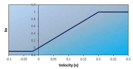
The velocity coefficient defines the relationship between headloss and velocity.
For normal and high headloss types, the relationship between kv and v is presented below:

| v | kv |
|---|---|
| < -0.02 | -0.1 |
| -0.02 to 0.2 | -0.1 + (v - (-0.02)) * (1.0 - (-0.1)) / (0.2 - (-0.02)) |
| >0.2 | 1.0 |
The headloss equation used for the fixed headloss condition is the same as for Normal and High headloss conditions:
|
|
|
In the fixed headloss case, the surcharge ratio coefficient ks is always set to 1.
The velocity coefficient kv defining the relationship between headloss and velocity is given as:
| v | kv |
|---|---|
| < 0.2 | -1 |
| > 0.2 | 1 |
This ensures that the loss is in the direction of flow when flow goes from the conduit into the node.
The headloss equation used for a user-defined headloss condition is the same as for Normal and High headloss conditions:
|
|
|
User-defined headloss curves are used to specify the relationship between:
- surcharge ratio and surcharge ratio coefficient ks
- velocity and velocity coefficient kv
See the Headloss Curve Data Fields topic for further information.
The FHWA headloss type is based on the FHWA Inlet and Access Hole Energy Loss method as described in section 7.1.6.7 of the FHWA HEC 22 Urban Drainage Manual. This headloss type is appropriate for closed conduits connected to manholes.
In order to use this method, the Benching method field should be set in connecting nodes and Headloss type set to FHWA at the appropriate link end of each pipe.
Notes
- The FHWA method assumes that the outflow pipe is circular; calculations use diameter. InfoWorks ICM uses conduit height to apply the model to non-circular outflow pipe shapes. (Conduit height used to set Do for use in equations 7-17, 7-18 and 7-19.)
- The FHWA method needs to know the angle between inlet pipe(s) and the outlet pipe to calculate the additional angle flow loss coefficient Cq (equation 7-23). InfoWorks ICM calculates the bearing of each line end relative to the node it is attached to in order to determine Cq.
- The FHWA method calculates the energy grade line (EGL) through the manhole rather than the hydraulic grade line (HGL). InfoWorks ICM sets the water level in manholes to EGLa (equation 7-30) giving a conservative estimate of level.

