Inlet Node Parameters
The data fields in the Gully/Inlet Parameters section of the Node Property Sheet are used when defining an Inlet Node using the Inlet Input Type of Params. The data required to calculate the flow intercepted at the node depends on the type of inlet being modelled.
Continuous Grade Inlets
Continuous grade inlets are modelled based on the inlet's efficiency at intercepting flow.
The equations used by InfoWorks ICM to calculate interception of flow are based on the equations from the FHWA HEC 22 Urban Drainage Manual.
The inlet parameter values required on the Node Property Sheet are:
- Cross slope
- Width of grate
- Length of grate
- Velocity where splash-over first occurs
A clogging factor may also be specified. The clogging factor is equivalent to the percentage reduction in flow that the grate can take.
If the inlet is drowned (Level > min(Ground level, Bottom storage level) or has reverse flow (Level > Overland Level) then the orifice equation from the Sag Grate Inlet is used with the open area taken as 0.8LW (a nominal reduction averaged over many inlet types).
|
|
Efficiency expressed as a ratio:
where: Rf = ratio of frontal flow intercepted to total frontal flow Rs = ratio of side flow intercepted to total side flow E0 = ratio of frontal flow to total gutter flow Rf is calculated as:
where: Ku = 0.295 (0.09 imperial units) V = velocity of flow in gutter, m/s (ft/s) (V is either DS velocity or US velocity in the overland link depending on which end is connected to the inlet node. If two overland links are connected to the inlet and have flow towards the inlet, V is the sum of the velocities from each of the overland links) V0 = gutter velocity where splash-over first occurs (m/s) Note Rf cannot exceed 1.0
Rs is calculated as:
where: Ku = 0.0828 (0.15 imperial units) V = velocity of flow in gutter, m/s (ft/s) Sx = road cross slope, m/m (ft/ft) L = length of the grate, m (ft)
E0 is calculated as:
where: W = width of depressed gutter or grate, m (ft) T = total spread of water and is calculated from:
where: d= Overland Level - min(Ground level, Bottom storage level), m (ft) Sx = road cross slope, m/m (ft/ft) |
The equations used by InfoWorks ICM to calculate interception of flow are based on the equations from the FHWA HEC 22 Urban Drainage Manual.
The inlet parameter values required on the Node Property Sheet are:
- Length of curb opening
- Cross slope
To model a depressed inlet, values for the following parameters are also required:
- Gutter depression
- Lateral width of gutter depression
For drowned-forward or reverse flow, either drowned weir or orifice flow is used as for the Sag Curb-opening inlet with a nominal opening height of 100mm. The undepressed weir equation is used for weir flow.
|
|
Efficiency expressed as a ratio:
where: L = curb opening length, m (ft) LT = length of curb opening inlet required for total interception of gutter flow, m (ft)
LT is calculated as:
where: Ku = 1.469 Sx = road cross slope, m/m (ft/ft) Q = gutter flow, m3/s (ft3/s) (Q is either DS flow or US flow in the overland link depending on which end is connected to the inlet node. If two overland links are connected to the inlet and have flow towards the inlet, Q is the sum of the flows from each of the overland links) d = Overland Level - min(Ground level, Bottom storage level), m (ft)
To find LT for a depressed curb-opening inlet replace Sx by Se, the equivalent cross slope, where Se is calculated as:
where: S'w = gutter depression/Lateral width of gutter depression, m/m (ft/ft) E0 = ratio of frontal flow to gutter flow as described in Equation 4 for Grate inlet above Note: If either of the gutter depression values are zero, S'w is set to zero. |
The UPC (Universitat Politècnica de Catalunya) Grate may be used as an alternative to the HEC-22 continuous grate (ContG) inlet.
The equations used by InfoWorks ICM to calculate interception of flow are based on the equations from the work carried out by Gomez, M. and Russo, B. (2011).
The inlet parameter values required on the Node Property Sheet are:
- Cross slope
- Width of grate
- Length of grate
- Number of bars (transverse, lateral, diagonal)
- Minimum area including voids
- Area of voids
|
|
UPC equation:
where: Qi = flow intercepted (m3/s) Qroadway = flow approaching the inlet (m3/s) y = flow depth upstream of the inlet (m)
A is calculated as:
where: Ag = area of grate voids if bars were removed (m2) p = ratio of void areas (AH) and Ag (%) AH = area of grate voids (m2) nt = number of transverse bars nl = number of longitudinal bars nd = number of diagonal bars
B is calculated as:
where: L = inlet length (cm) W = inlet width (cm) |
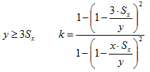
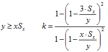
The equation for calculating k, differs depending on road width (x). Note that this width is usually half the full width of the road as there are assumed to be gullies along both kerbs.

InfoWorks ICM interprets x as the full width of the connected link as it is expected that each half of the road will be modelled separately, or the number of gullies will be doubled to reflect the fact that they exist on both sides of the road.
|
|
Half roadway width x = 3m
Half roadway width x < 3m
Half roadway width x > 3m
where: x = width of half the roadway Sx = cross slope |
As described above, continuous inlets require information from the roadway when using the Inlet input type of Params:
- Continuous Grate Inlet – inflow and velocity
- Continuous Curb-Opening Inlet - inflow
- Continuous UPC Grate Inlet – inflow, half road width (x)
When modelling the node as a 1D inlet, flow in road, Q, is determined from the flow in the overland conduits connected to the upstream end of the inlet.
For 2D inlets, it is necessary to specify a Cross slope in order to calculate inflow.
|
|
Inflow is calculated as:
where: v = velocity in mesh element containing inlet node
Inflow area, A is calculated as:
where: d = depth in mesh element containing inlet node T = spread (or width of flow perpendicular to the gutter edge)
T is calculated as:
where: Sx = cross slope (supplied by user) |
The UPC grate also requires a Half road width value to be specified for a 2D inlet. (When modelling the node as a 1D inlet, InfoWorks ICM interprets x as the full width of the connected link.)
Sag Inlets
Sag inlets are modelled as weirs up to a certain depth and then are modelled as orifices.
A user defined value for the depth of water up to which gate behaves as weir is required for all sag inlet types.
The equations used by InfoWorks ICM to calculate interception of flow are based on the equations from the FHWA HEC 22 Urban Drainage Manual.
The inlet parameter values required on the Node Property Sheet are:
- Width of grate
- Length of grate
- Clear opening area of grate
A clogging factor may also be specified. The clogging factor is equivalent to the percentage reduction in the width of the grate.
|
|
Weir equation:
where: Qi = flow intercepted, m3/s (ft3/s) P = perimeter of gate disregarding the curb calculated as W + W + L where: W = width of grate, m (ft) L = length of grate, m (ft) Cw = 1.66 (3.0 imperal units) d = Overland Level - min(Ground level, Bottom storage level), m (ft) W = width of grate, m (ft) Sx = Cross slope
Orifice equation:
where: C0 = 0.67 Ag = clear opening area of grate, m2 (ft2) g = 9.81 m/s2 (32.16 ft/s2) d = Overland Level - min(Ground level, Bottom storage level), m (ft) W = width of grate, m (ft) Sx = Cross slope |
The inlet parameter values required on the Node Property Sheet are:
- Length of curb opening
- Lateral width of gutter depression
- height of curb opening
|
|
Depressed Inlet - Weir equation:
where: Qi = flow intercepted, m3/s (ft3/s) Cw = 1.25 (2.3 imperial units) L = length of curb opening, m (ft) W = lateral width of depression, m (ft) d = Overland Level - min(Ground level, Bottom storage level), m (ft)
Undepressed Inlet - Weir equation (used if length of inlet > 3.6 m):
where: Cw = 1.6 (3.0 imperial units)
Depressed Inlet - Orifice equation:
Undepressed Inlet - Orifice equation:
where: C0 = orifice coefficient 0.67 d = Overland Level- min(Ground level, Bottom storage level), m (ft) L = length of orifice opening, m (ft) Ag = clear area of opening, m2 (ft2) = hL h = height of curb-opening orifice, m (ft) |
The weir equation used for the Combination Inlet is the same as the weir equation used for the grate inlet weir given as equation 9 above.
The inlet parameter values required on the Node Property Sheet are:
- Width of grate
- Length of grate
- Clear opening area of grate
- Height of curb opening
- Length of curb opening
A clogging factor may also be specified. The clogging factor is equivalent to the percentage reduction in the width of the grate.
|
|
Orifice equation:
where: Ag = clear area of opening, m2 (ft2) g = 9.81 m/s2 (32.16 ft/s2) d = Overland Level - min(Ground level, Bottom storage level), m (ft) h = height of curb opening, m (ft) L = length of curb opening, m (ft) |


