Inlet Nodes
Inlet Nodes are used to model storm drain inlets. These inlets intercept flow from the overland system and pass it to the underground storm drainage system. Inlets are typically located in roadside gutters.
Modelling Inlet Nodes
To define a node as an Inlet in InfoWorks ICM, select the Inlet option in the Flood Type field of the Node.
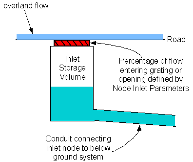
The inlet defines the amount of overland flow discharging into the node storage volume. The amount intercepted is calculated according to a set of specified inlet parameters.

Schematic Diagram of Inlet Node
The link type connected to the inlet node must be of type overland if flow into the node is to be controlled by the inlet. For any other link type, the inlet parameters will be ignored and flow will pass straight through the inlet as if it were a manhole. This allows modelling of connections feeding directly into the drainage system at the node.
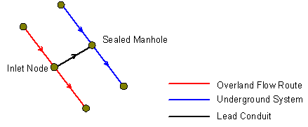
The inlet storage may be connected to the underground drainage system via a 'lead' conduit which may act as a constriction to flows entering the drainage system. If no lead conduit is modelled, it is assumed that one does not exist and therefore no constriction is modelled between the inlet and the main system.

Inlet with Lead Conduit Modelled
Inlet Type
The type of inlet to be modelled is selected from the Inlet Type field on the Inlet tab of the Node Property Sheet.
The types of inlet that can be modelled in InfoWorks ICM are:
- Grate Inlet - opening in gutter covered by a grate
- Curb-opening inlet - vertical opening in curb covered by a top slab
- Combination inlet - both curb-opening inlet and grate inlet placed side by side
Grate inlets and curb-opening inlets can be modelled as either a continuous grade inlet (located on a slope) or as a sag inlet (located in a dip in the road). Combination inlets can be modelled as a sag inlet.
Inlet Input Type
The method of calculating the flow intercepted by the inlet node is selected from the Inlet Input Type field on the Inlet tab of the Node Property Sheet:
Relationship between head at the inlet node and discharge to the inlet is defined by a Head Discharge Table. This method is implemented in the same way as for gully nodes.
Relationship between depth of flow at the inlet node and discharge to the inlet is defined by an equation in the form of:
Q=ayb
Where:
Q = flow
a = constant defined in User Equation A value field
y = depth of flow at inlet
b = constant defined in User Equation B value field
Relationship between flow at the inlet node and the fraction of flow that the inlet will intercept is defined by a Flow Efficiency Table.
Efficiency value is multiplied by flow to obtain flow intercepted by gutter.
|
|
where: QI = interception capacity of gutter E = efficiency Q = flow in road |
2D Inlets using flow efficiency
When modelling the node as a 1D inlet, flow in road, Q, is determined from the flow in the overland conduits connected to the upstream end of the inlet.
For 2D inlets, it is necessary to specify a Cross slope in order to calculate inflow.
|
|
Inflow is calculated as:
where: v = velocity in mesh element containing inlet node
Inflow area, A is calculated as:
where: d = depth in mesh element containing inlet node T = spread (or width of flow perpendicular to the gutter edge)
T is calculated as:
where: Sx = cross slope (supplied by user) |
Flow intercepted at the inlet node is calculated based on equations from the FHWA HEC 22 Urban Drainage Manual for the majority of inlet types.
For the continuous UPC grate inlet, calculations are based on the research carried out by Gomez, M. and Russo, B. (2011).
Values for parameters in these equations are entered in the Gully/Inlet Parameters section of the Property Sheet.
See the Inlet Node Parameters topic for details of equations and the values required for each inlet type.
Flow limiting at 2D inlets
When modelling 2D inlets, flow capping will be applied to limit exchange between the 2D and 1D network in situations where inflow at the node would exceed volume contained in the 2D element at any given timestep. This may occur if the 2D element that the inlet node is located within is too small.
Nodes at which flow limiting has been applied can be identified from the Duration of flow limiting node result; flow limiting has been applied if Limiting duration is greater than zero. The Total cumulative limited volume result indicates the severity of the capping procedure (over the entire simulation) as a volume.
Additional time varying results are made available when the Timestep log option on the Run Diagnostics Dialog is turned on:
- The Flow limited result is set to 1 when capping is applied and 0 when capping is not applied
- The Cumulative limited volume indicates the severity of the capping procedure, at each timestep, as a volume
- Cumulative limited volume rate is the rate of change of cumulative limited volume derived from the Cumulative limited volume results
A warning will appear in the log if flow limiting has been applied.
