RTC CENTAUR Example
This RTC option allows for the CENTAUR™ gates developed by Environmental Monitoring Solutions to be represented and for the logic in their controls to be replicated in InfoWorks ICM. The idea behind the gates is that there is a flooding location downstream to be protected, as well as a level sensor directly upstream of the gate itself. There are no further inputs to the gate control and the position is modified in response to given levels to protect the flooding location.
To configure a CENTAUR gate in InfoWorks ICM:
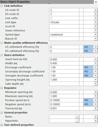
- Ensure that a variable sluice gate gate is included in the InfoWorks network. The properties for the sluice gate should match the physical properties of the gate which is being considered for deployment or already in operation in the network.

- In the RTC Window Editor, use the Insert Regulator option from the popup menu to add this gate as a regulator in the RTC. This can be at the Regulator or Global level.
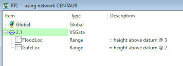
- Add the following ranges:
- the flooding protection location downstream of the gate
- the node location directly upstream of the gate
Typically the flooding location range will be set to have a minimum level equivalent to the level at which the gate is first desired to become active and implement the CENTAUR logic. The gate level will also be defined to have a minimum level; one at which it is desired for the CENTAUR logic to become active.
When the ranges have been specified (thereby setting the conditions under which the RTC should take effect):
- Specify an OR logic statement. This provides the ability to reference either the flood location or the gate location exceedance of minimums becoming true.

- Set the actual target levels and parameters for the controller in the RTC Controller pane as follows:
- Enter a name, up to 10 characters in length, for this control in the Name field.
- Select the CENTAUR option from the Type field.
- Specify the measurement and control interval in seconds for the RTC in the Interval field. This must be a multiple of the timestep used in the applicable simulation.
- Specify the flood location range that is being protected in the Target range field. This was defined in step 3.
- Specify the gate location range that is being protected in the Gate range field. This was defined in step 3.
- Specify the level that the flood location is being protected to in the Target max field.
- Specify the level that the gate location should not exceed in the Gate max field.
- Specify the maximum change accepted for the flood level location in the Target change max field.
- Specify the maximum change accepted for the gate location in the Gate change max field.
- Specify a value of -10 for CENTAUR in the fuzzy logic Min output (%) field.
- Specify a value of 50 for CENTAUR in the fuzzy logic Max output (%) field.
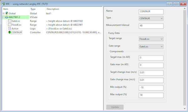
- Add two Rules records:
- The default rule for when the CENTAUR controller is not active. This is a POS Type of rule that sets the gate to its fully open position.
- The active rule. The condition should be set to reference the logic (the flood location range and/or the gate location range to be true) which was defined in Step 4. The Type should be set to CTRL, and the Controller set to the CENTAUR controller defined in step 5.

 Note
NoteThe gate will usually be open and only start controlling once certain trigger thresholds are breached for the flooding or gate locations.