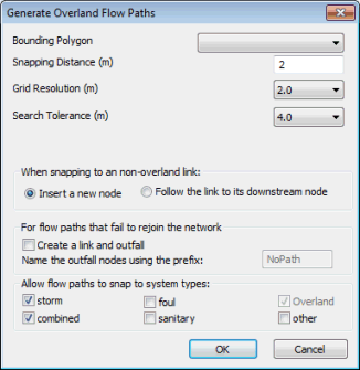
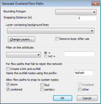
Generate Overland Flow Paths Dialog
This dialog is used to automatically create overland links and nodes based on a starting selection of nodes, an (optional) bounding polygon, and a gridded Ground Model or GIS background layer containing lines.
The dialog is displayed when an option is selected from the Generate 1D overland flow paths menu from the Model menu. The dialog options differ depending on the option chosen.
See Generating Overland Flow Paths for further details.
|
Dialog Option |
Description |
|---|---|
|
Bounding Polygon |
A dropdown list of polygons in the network. If a Bounding Polygon is selected:
|
|
Snapping Distance |
The distance to a link / node or background layer line that overland flow path must be within, before snapping will be allowed. |
|
Layer containing background lines |
Applicable to generation of Overland Flow Paths from Background Layer Lines only. Dropdown list containing GIS layers currently loaded on the GeoPlan. Click the Change Layers button to display the GIS Layer Control Dialog. Check the Remove layer after import box to automatically unload the layer after flow path generation. |
|
Filter on line attribute: |
Applicable to generation of Overland Flow Paths from Background Layer Lines only. Dropdown list of fields in the selected layer table. Only lines filtered by the selected attribute will be used for generation of flow paths. |
|
Grid Resolution |
Applicable to generation of Overland Flow Paths from Ground Model only. Dropdown list containing multiples of base cell size of the current Gridded Ground Model in powers of two up to 10 x default Snapping Distance. Selecting a resolution of larger cell size may aid inference of flow direction to avoid termination of flow paths in local pits. |
|
When snapping to a non-overland link: |
Applicable to generation of Overland Flow Paths from Ground Model only. The options when the overland flow path is within Snapping Distance of a non-overland link / node are to:
When snapping to an Overland link a new node will always be inserted. |
|
For flow paths that fail to rejoin the network |
Check the Create a link and outfall box to create an overland link and outfall for flow paths that do not snap to the existing network. Links and Outfalls will be created if:
The created outfall node names will be prefixed by the text entered in the Name the outfall nodes using the prefix: box, followed by four figures: 0001, 0002 etc. |
|
Allow flow paths to snap to system types: |
The overland flow path will only be snapped to an existing system if the existing link / node within Snapping Distance is of one of the system types selected in this section. The option to snap to system type "Overland" is always selected. |


