step 4 - Adding bank spill sections

This stage assumes that you have started InfoWorks ICM and that the Explorer window is open, showing the River example network icon. You should complete the previous stages before starting this stage. If you want to work with the prepared example data, load the appropriate version of the network. For instructions on how to load the database, see Opening the Example Database.
 Back to previous stage.
We are now going to add a storage node and an associated storage area.
- Ensure that the River example network and the DTM ground model are both open on the GeoPlan. Alternatively, if you have not completed the previous steps, please use the provided River example - step 3 completed network as a starting point.
- Start by adding a new storage node:
- Select Node in the New Object Type dropdown list and click on the New Object button (
 ). Both controls can be found on the GeoPlan Tools toolbar.
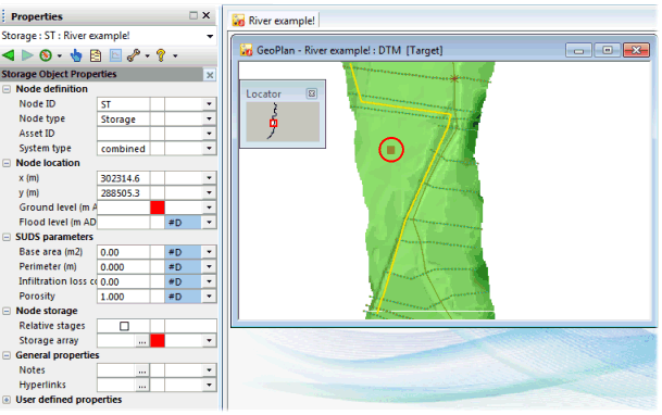
 - Place the node approximately at the location shown on the screenshot below.
- In the Create New Node dialog, name the node ST and give it a Type of Storage.
- Click on OK.
- There are two red on-the-fly validation warnings in the storage node property sheet:
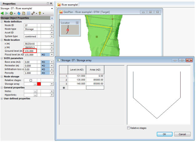
- Ground level - Set the ground level to 131mAD.
- Storage array - set up the storage array as described below:
- For this click on the
 button adjacent to the Storage array section.
 - The Storage area dialog is displayed.
- Set Level/Area values of (131.0 mAD, 0 m2), (135.0 mAD, 85000 m2) and (140.0 mAD, 85000 m2).
- Click on OK on the dialog to save your changes.
- You will notice that the validation warnings have disappeared.
- For this click on the
- Select Node in the New Object Type dropdown list and click on the New Object button (
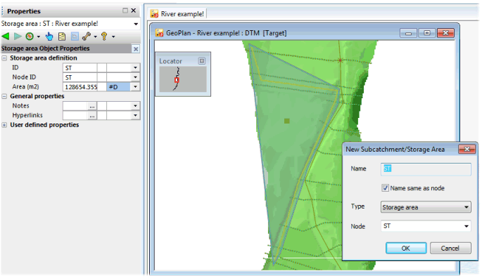
- Next we are going to add a storage area. The boundaries of the storage area should overlap the river bank.
- Select Subcatchment/Storage in the New Object Type dropdown list and click on the New Object button (
 ).
). - Digitise the polygon as shown in the screenshot and double-click to finish.
- In the New Subcatchment/Storage area dialog, ensure that the Same name as node check box is ticked and that the storage node added in the previous step is specified in the Node dropdown list.
- Click on OK.
- Select Subcatchment/Storage in the New Object Type dropdown list and click on the New Object button (
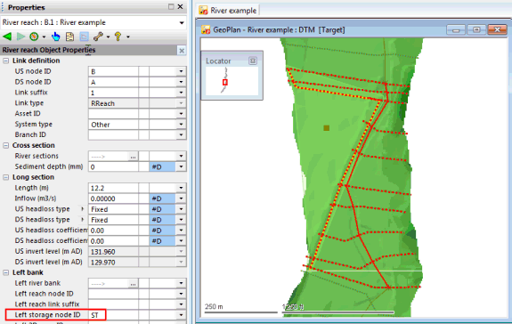
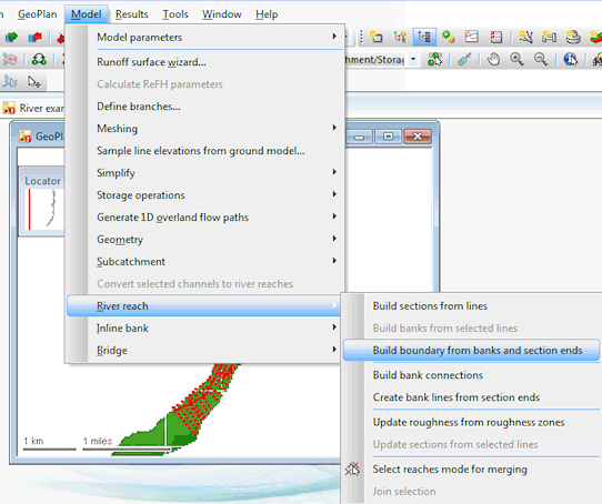
- Next we need to select the river reach and select the Build bank connections option from the Model then River reach menu to connect the bank to the storage area. This populates the Left storage node ID field of the river reach property sheet with the name of the storage node.
- The final stage in building a river reach is to define an overall river boundary to allow for flood mapping once a simulation has been run. The boundary is built by joining up bank lines where they exist and section ends where they do not. Select the three river reaches and build the reach boundaries by using Model | River reach | Build boundary from bank and section ends.
- Let us now commit the changes made to the model:
- In the Explorer window, right-hand click on the River example network and select Commit changes (save to master).
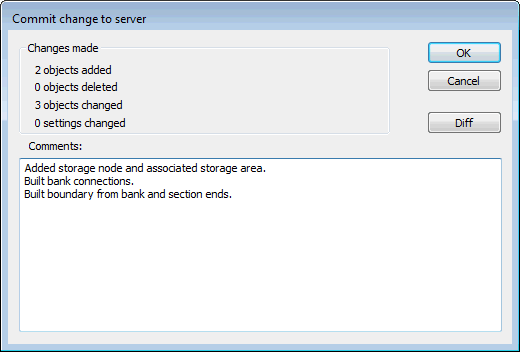
- The Commit change to server dialog is displayed.
- Type in any notes as appropriate.
- Click on OK to commit the changes and close the dialog.
- If a message is displayed asking you if you wish to validate the network at the same time as you are committing your changes, click on No for now. We will validate the network at a later stage.
You now have all the data you need to run a simulation.
 Back to River Tutorial main page.
