step 5 - Running simulations on the river model

This stage assumes that you have started InfoWorks ICM and that the Explorer window is open, showing the River example network icon. You should complete the previous stages before starting this stage. If you want to work with the prepared example data, load the appropriate version of the network. For instructions on how to load the database, see Opening the Example Database.
 Back to previous stage.
The network should be validated and committed before running any simulation.
- Validate the River example network:
- Ensure the network and the DTM ground model open in the GeoPlan. Alternatively, if you have not completed the previous steps, please use the provided River example - step 4 completed network as a starting point.
- Select the Validate button (
 ) on the Validation toolbar.
 - The Network Validation dialog is displayed.
- Click on OK.
- There should be no errors highlighted in the Output window.
- Before committing the network, we need to make minor changes to some simulation parameters:
- Select Model parameters, then Simulation parameters from the Model menu.
- Change the Maximum space step to 20m, the Phase-in time to 150min and the Steady state flow tolerance to 0.01.
- Commit the network:
 Tip
Tip Note that for the purpose of this tutorial, we have been committing changes regularly, at every step so that it is easier for the user to revert to a previous committed version, or to compare different versions of the network. Please refer to the Viewing the Commit History topic for more detail.
- In the Explorer window, right-hand click on the network and select Commit changes (save to master).
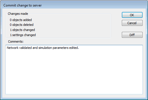
- The Commit change to server dialog is displayed.
- Type in any notes as appropriate.
- Click on OK.
- We now need to add flow to our model using an inflow hydrograph. We are going to create a new inflow event.
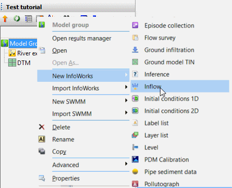
- Create a new inflow object by right-hand click the Model Group in the Explorer window.
- Select New InfoWorks | Inflow.
- In the New Name - Inflow dialog, type in Inflow and click on OK.
- Drag and drop the Inflow object onto the InfoWorks ICM background.
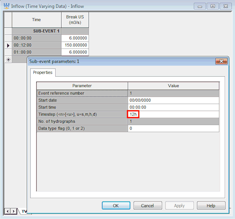
- Right click anywhere in the sub-event and choose Sub-event properties from the popup menu.
- Set the timestep to 12h. Click on OK to save.
- Back in the Inflow editor, set three flow values, 6.0 m3/s, 150 m3/s and 6.0 m3/s.
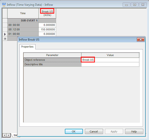
- Right click anywhere in the sub-event and choose Profile properties from the popup menu.
- The Object reference is the most upstream node (Break US) as shown above.
- Click on the
 button to close the editor. Click on Yes on the Save changes to data message.
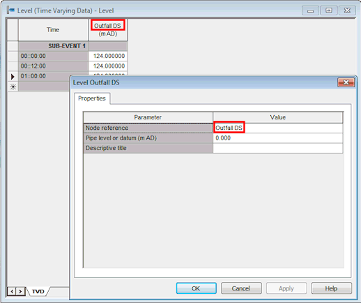
- We will set the downstream stage using a Level hydrograph. Create a new level object and in the same way as you applied the inflow to the most upstream node, apply the level file to the most downstream node (Outfall DS):
- Right-hand click the Model Group in the Explorer window.
- Select New InfoWorks | Level.
- In the New Name - Level dialog, type in Level and click on OK.
- Drag and drop the Level object onto the InfoWorks ICM background.
- Right-click on the sub-event data and choose Profile Properties from the popup menu.
- Type the outfall-node name in the Node reference cell.
- Click on OK to save your changes. The profile name matches the downstream node name.
- Right-click on the sub-event data and choose Sub-event properties from the popup menu.
- Set the timestep to 12h and click on OK.
- Back in the Level editor, set three constant level values of 124.0 mAD.
- Click on the
 button to close the editor. Click on Yes on the Save changes to data message.
- A simulation can now be scheduled:
- Ensure the Job Control window is visible. If not, click on the Job control window button (
 ) of the Docking Windows Toolbar. The Job Control Window displays the order and status of scheduled simulations.
 - Create a new run by right-hand clicking the Model Group in the Explorer window:
- Select New InfoWorks | Run. The Schedule Hydraulic Run View dialog is displayed.
- In the Schedule Hydraulic Run View dialog:
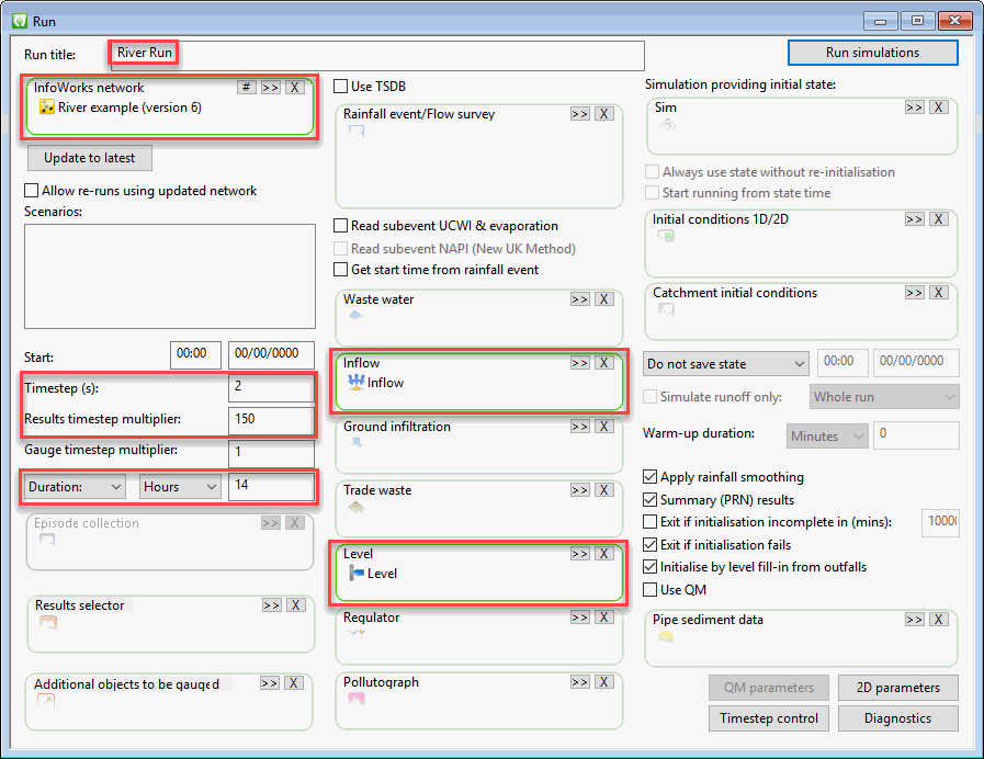
- Enter a name in the Run title (River Run)
- Drag and drop your network (River example or River example - step 5 completed) in the InfoWorks Network drop target.
- Drag and drop the Inflow hydrograph in the Inflow drop target.
- Drag and drop the Level hydrograph in the Level drop target.
- Set the Timestep to 2 seconds and the Results timestep multiplier to 150.
- Set the Simulation time as 14 hours.
- Use all other suggested defaults.
- Press the Run simulations button.
- On the Schedule Job(s) dialog, choose which computer will carry out the simulation (This Computer) and leave the other parameters as they are (store results locally and start the simulation now). Press OK to start.
- Ensure the Job Control window is visible. If not, click on the Job control window button (
- Once the simulation has completed (the simulation icon in the Explorer window will turn from blue to green and the Job Control window will show a green row with a status of Succeeded for the simulation) you can look at and analyse the results by dragging and dropping the DWF simulation onto the main window.
The simulation has created a large number of results, which you can now inspect.
 Back to River Tutorial main page.
