step 5 - Viewing a bridge in InfoWorks ICM

Note
This stage assumes that you have started InfoWorks ICM and that the Explorer window is open, showing the Adding a bridge network icon. You should complete the previous stages before starting this stage. If you want to work with the prepared example data, load the appropriate version of the network. For instructions on how to load the database, see Opening the Example Database.
 Back to previous stage.
- Ensure that the Adding a bridge network and the DTM ground model are both open on the GeoPlan. Alternatively, if you have not completed the previous steps, please use the provided Adding a bridge- step 4 completed network as a starting point.
- To view the bridge opening:
- Click on the Properties Tool (
 ) from the GeoPlan Tools toolbar and then click on the bridge opening on the GeoPlan.
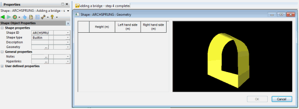
 - In the bridge opening property sheet, click on the small arrow adjacent to Shape ID and select Open shape ARCHSPRUNG. The "Archsprung" shape property sheet is displayed.
- Click on the
 button adjacent to Geometry.
 - The Shape dialog is displayed.
- Close the Shape dialog by clicking on the
 button.
- Click on the Properties Tool (
- The completed bridge can also be viewed:
- Click on the Properties Tool (
 ) from the GeoPlan Tools toolbar and then click on the bridge on the GeoPlan.
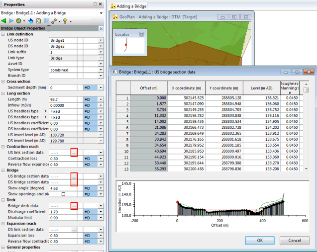
 - The bridge property sheet is displayed. Click on the
 button adjacent to US link section data, US bridge section data, DS bridge section data, Bridge deck data, or DS link section data to view the corresponding data.
 - Once you have finished looking at the data, either click on the
 button or the OK button to close every dialog.
- Click on the Properties Tool (
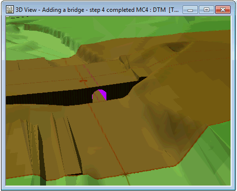
- The bridge can also be viewed in 3D:
- Zoom to the area to be viewed by using the Zoom in tool (
 ) of the GeoPlan Tools toolbar.
 - Click on the 3D Network Window tool (
 ) on the Windows toolbar to open a 3D window of the bridge.
 - Close the 3D view by clicking on the
 button.
- Zoom to the area to be viewed by using the Zoom in tool (
You now have all the data you need to run a simulation.
 Back to Bridge Tutorial main page.


