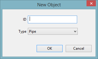
Create New Object Dialog
When digitising a new network object on the GeoPlan window, a 'Create New Object' dialog is displayed to let you specify information about the object.
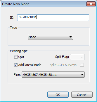
Displayed when digitising a new node on the GeoPlan or Long Section Window to create a new node.
Enter a unique identifier for the node (the node ID will be automatically populated if Automatic Node Name Generation is switched on).
Select node Type from the dropdown list.
Nodes may be inserted into an existing pipe by checking the Split box. Select the pipe to be split from the Pipe: dropdown list and set a flag for calculated pipe lengths and invert levels if required. When working with Collection Networks, the option to automatically split CCTV Surveys associated with the link to be split is also available.
Nodes may be added as lateral nodes to a pipe by checking the Add lateral node box. Select the pipe to which the node is to be added from the Pipe: dropdown list.
When working with Distribution Networks, the option to specify a Pump Station ID is made available when creating a pump object.
Displayed when digitising a new link on the GeoPlan Window.
The Upstream Node ID and Downstream Node ID are automatically filled in from the nodes that you clicked on. You can enter a specific suffix if you want. If you leave this field blank, InfoAsset Manager will allocate a suffix for you.
When working with Collection Networks, the option to specify a Pump Station ID is made available when creating a pump object.
Displayed when digitising a new line on the GeoPlan Window.
Enter a unique identifier for the line.
Choose the type of line from the Type dropdown list.
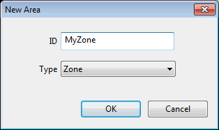
Displayed when digitising a new
Enter a unique identifier for the
Choose the type of
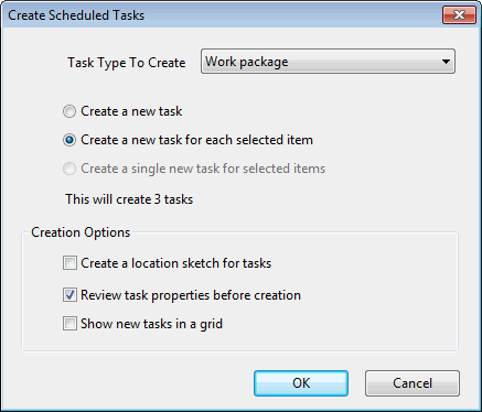
Displayed when digitising a new survey or repair task, or a work package on the GeoPlan to create a new scheduled task.
Choose the task type from the Task Type to Create dropdown list.
Please refer to the Create Scheduled Tasks Dialog topic for more information on the other options available on the dialog.
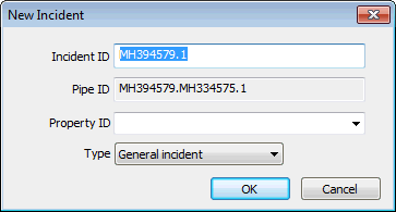
Displayed when digitising a new incident on the GeoPlan Window.
A default Incident ID based on the associated node or pipe ID is displayed in the dialog.
If the incident is associated with a node the default Incident ID takes the format of x.n where x is the ID of the associated node and n is an index used to make the incident ID unique.
If the incident is associated with a pipe the default Incident ID takes the format of x.n where x is the US Node ID of the associated pipe and n is an index used to make the incident ID unique.
If the incident is associated with a connection pipe the default Incident ID takes the format of x.n where x is the ID of the associated connection pipe and n is an index used to make the incident ID unique.
If the incident is not associated with an asset:
- the Incident ID is generated by Automatic Node Name Generation, if automatic node naming is switched on
- the Incident ID is generated as .n if automatic node naming is switched off, where n is an integer used to make the Incident ID unique.
 Advice for avoiding conflicts
 Switch Automatic Node Name Generation on when adding Incidents that are not associated with assets to avoid conflicts when committing changes to the network.
If the incident is created in the location of one or more Property objects, an associated property can be selected from the Property ID dropdown list (this does not apply to asset networks).
Displayed when digitising a new survey associated with a pipe (CCTV Survey, Dye Test Survey or Smoke Test Survey) on the GeoPlan Window.
The default Survey ID takes the format of xy.n where x is the US Node ID and y is the Link Suffix of the associated pipe and n is an index used to make the survey ID unique.
An upstream direction is assume for CCTV surveys.
Displayed when digitising a new pipe repair on the GeoPlan Window.
A default Pipe Repair ID based on the associated pipe ID is displayed in the dialog.
- Collection Networks: The default Pipe Repair ID takes the format of xy.n where x is the US Node ID and y is the Link Suffix of the associated pipe and n is an index used to make the repair ID unique.
- Distribution Networks: The default Pipe Repair ID takes the format of x.n where x is the ID of the associated pipe and n is an index used to make the repair ID unique.
Displayed when digitising a new survey associated with a node (Monitoring Survey or Manhole Survey) or Manhole Repair on the GeoPlan Window.
If the survey or repair has been created at the location of a Node / Manhole object, a default ID will be displayed on the dialog. The default ID is the ID of the associated Node / Manhole.
Displayed when digitising a new Asset Point on the GeoPlan Window.
Enter a unique identifier for the asset point and select asset point Type from the dropdown list.
When creating a Generator object the option to specify a Pump Station ID is made available.
Displayed when the New object context menu option is selected for a relationship group on the Object Browser Window.
Enter a unique identifier for the object and select a Type from the dropdown list (depending on the type of the object in the relationship group selected, there may be one or several available object types).
See Using the Object Browser Window for more information.
