Bridges in ICM
In the InfoWorks ICM user interface, a bridge object is represented as a single object comprised of a link between two nodes (defining the centre line of the bridge) and an associated polygon.
Five cross sections are defined at the link representing:
- upstream end of the link, located at the upstream end of the contraction zone
- upstream face of the bridge, at the toe of the embankment
- downstream face of the bridge, at the toe of the embankment
- downstream end of the link, located at the downstream end of the expansion zone
- bridge deck
Bridge opening objects and inlet and outlet objects may also be associated with the bridge link.
(See Bridges topic for further details.)

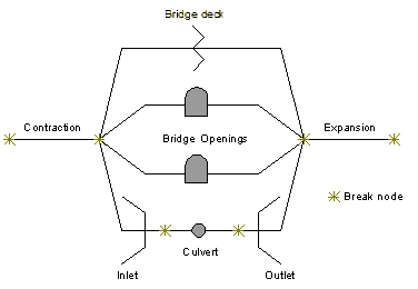
In the simulation engine, the bridge object is modelled as a set of objects as described in the schematic below.

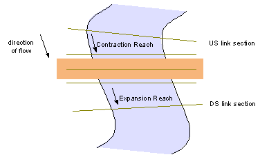
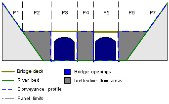
- Contraction reach consisting of two sections and user-supplied loss coefficients with ineffective flow areas blocking the conveyance parts of the downstream section
- A node
- In parallel:
- A conduit link for each bridge opening, with piers and a user-supplied pier loss coefficient
- An entry, an exit and a conduit for each culvert
- An irregular weir for overtop flow
- A node
- Expansion reach consisting of two sections and user-supplied loss coefficients, with ineffective flow areas blocking the conveyance parts of the upstream section
Contraction and Expansion Reaches
The contraction reach from upstream end of link (full width upstream) to upstream bridge face and expansion reach from downstream bridge face to downstream end of link (full width downstream) are modelled in a similar way to river reaches, with additional support for ineffective flow areas and contraction and expansion losses.
Ineffective flow areas
Ineffective flow areas represent the areas outside of openings where no flow occurs until overtopping of the road deck occurs.
InfoWorks ICM determines the ineffective flow areas from bridge opening geometry. For example, a single opening bridge will have two ineffective flow areas: one from the left bank to the left of the bridge opening, and one from the right of the bridge opening to the right bank.

Contraction and expansion losses
Contraction and expansion losses are energy losses associated with the change in the shape of river sections or effective flow area.
The losses are calculated by multiplying a user defined loss coefficient by the absolute value of the change in velocity head between the pair of sections.
Each contraction and expansion reach has two fields for user defined loss coefficients, one for contracting flow, and one for expanding flow to allow reverse flow into account.
Bridge deck
The profile of the bridge deck is defined in the Bridge deck data of the bridge object.
InfoWorks ICM models flow over the bridge deck as flow over an Irregular weir.
Bridge openings
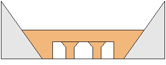
The location of openings in the bridge section are specified via the Bridge property sheet. The geometry of an opening is defined as a Bridge Opening object. The geometry and location of piers within each opening can also be defined in the Bridge Opening object. Bridge openings can be associated with bridge sections manually by entering details in the Bridge property sheet, or by using the Build bridge openings tool.
Bridge openings are modelled by using the standard conduit methodology (see the Hydraulic Theory topic) with added support for non-prismatic openings and the presence of piers.

Where piers are defined within the opening, the section geometry of the conduit representing the opening is determined as follows:
- subtract pier area from conduit area
- subtract total pier width from conduit width
- add wetted perimeter for pier sides
- subtract wetted perimeter at invert and soffit
Roughness values are required for both opening and pier surfaces. An equivalent friction factor is determined for the whole wetted perimeter. A fixed headloss may also be defined in the Bridge Opening object to represent pier losses.
Culverts
InfoWorks ICM models culverts as a sequence of culvert inlet, conduit and culvert outlet.
Culvert inlet and outlet properties are defined as Bridge Inlet and Bridge Outlet objects respectively. The inlet and outlet objects are associated with a bridge opening via the Inlet ID and Outlet ID fields of the opening.
