Hydraulic Theory
The sections below contain details of the InfoWorks ICM 1D hydraulic model equations used for InfoWorks networks and how they are solved.
For details of equations used by the 2D engine, see the Basic 2D Hydraulic Theory topic, and the topic, 2D Conduits, for information about the equations when modelling flow using these type of conduits.
For details of the equations used by the hydraulic model for SWMM networks, refer to the latest version of the SWMM Reference Manual (Hydraulics), which can be downloaded from the EPA website.
The solution model for each conduit is selected from the Solution model field in the relevant property sheet.
A conduit is represented as a link in the network, of defined length, between two nodes. The boundary condition between the link and a node is either of the outfall or headloss type. The gradient of a conduit is defined by invert levels at each end of the link; this does not preclude discontinuities in level at nodes or negative gradients.
A variety of pre-defined cross-sectional shapes may be selected for both closed pipes and open channels. Circular pipes are defined by one dimension - the diameter - and all others by the height and width; in the case of open channels the height will be to the top of the channel lining. Non-standard cross-sectional shapes may be modelled by defining a non-dimensional height/width relationship.
Two different values of hydraulic roughness may be assigned; one for the bottom third of the conduit and one for the remainder. A permanent depth of sediment may be defined in the invert of the conduit; no erosion or deposition is considered.
The governing model equations are the Saint-Venant equations (see Yen, 1973). These are a pair of conservation equations of mass and momentum:
|
|
where Q - discharge (m3/s) A - cross-sectional area (m2) g - acceleration due to gravity (m/s2) q - angle of bed to horizontal (degrees) h - depth (m) S0 - bed slope K - conveyance (m3/s) |
The conveyance function is based on either the Colebrook-White or Manning expressions (see Wallingford Procedure).
The model equations governing pressurised pipe flow differ in that the free surface width is replaced conceptually by the relatively small term:
|
|
where B - free surface width (m) g - acceleration due to gravity (m/s2) Af - pipe full area (m2) Cp - pipe full velocity of water pressure wave (m/s) |
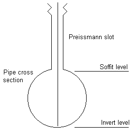
The solution of the Saint-Venant equations may be retained in pressurised flow by introducing a suitably narrow slot, the Preissmann slot, into the pipe soffit (see Cunge and Wegner, 1964). A smooth transition between free surface and surcharged conditions is thus enabled.
The Preissmann Slot is a conceptual vertical and narrow slot providing a conceptual free surface condition for the flow when the water level is above the top of a closed conduit.

The effect of placing the Preissmann slot directly onto the pipe soffit may be an abrupt change in surface width derivative and wave celerity in the transition to pressurised conditions. A transition region is included within the model defined by a monotonic cubic between the true pipe geometry and the width of the Preissmann slot.
The slot width itself is defined such that the wave celerity in the slot is ten times that at half the conduit height. This allows accurate modelling of pressurised flow (see Gomez et al., 1992) and results in a slot width that is 2% of the conduit width.

In a closed pipe the maximum conveyance will actually occur below the pipe soffit and will be greater than the 'pipe full' value. The conveyance approximates this by imposing monotonicity to avoid the turning point and the possibility of multiple numerical solutions.
You can use the pressurised pipe model instead of the full (Saint-Venant) solution on selected pipes: for example, if you wish to model rising mains or inverted siphons.
The model equations governing pressurised pipes are:
|
|
where Q - discharge (m3/s) A - pipe full area (m2) g - acceleration due to gravity (m/s2) h - piezometric depth (m) S0 - bed slope K - pipe full conveyance (m3/s) |
The pressurised pipe model more accurately predicts velocities and storage than the full (St. Venant) model because it does not assign base flow or a Preissmann slot to a pipe.
The Preissmann Slot is a conceptual vertical and narrow slot providing a conceptual free surface condition for the flow when the water level is above the top of a closed conduit.

Modelling the Inertia Term
InfoWorks ICM allows the user to select whether to model the inertia (dQ/dt) term in the dynamic equation or not.
To exclude modelling of the inertia term for pressure pipes, check the Drop inertia in pressure pipes option in the Simulation Parameters Dialog.
This feature can be used in conjunction with the Stay pressurised simulation parameters option to stop the occurrence of negative depths in force mains (rising mains).
This model is an advanced feature used to represent some pressurised systems. Please contact Innovyze Support for detailed information about when it is appropriate to use the ForceMain solution.
The ForceMain solution model is specified in the conduit's Solution model property.
It should only be used in pipes which are pressurised, usually those which receive pumped flow. It is useful for representing very long rising / force mains especially those subject to low hydraulic heads. It should not be used in gravity pipes.
The Force Main model assumes the pipe is always full (thereby enabling the pressurised pipe model whatever the flow conditions) although the hydraulic grade line can drop below the pipe soffit. Negative hydraulic grade lines do not automatically indicate erroneous results (see below).
The Force Main model uses the same equations as the Pressurised Pipe Model. Please refer to the Modelling of Pressurised Pipes topic for detailed information on these pressure equations. However, there are two assumptions in its application which do not apply to the pressurised pipe model.
- The water level is maintained at least to pipe soffit level at the interface between the ForceMain solution and the gravity solution, throughout the simulation. This can lead to a large erroneous generation of flow if the model is used in inappropriate locations. Please contact the support team for further details.
- At the end of the initialisation process (the start of simulation) the Force Main model will be implemented, even if the pipe is not completely full.
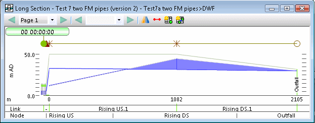
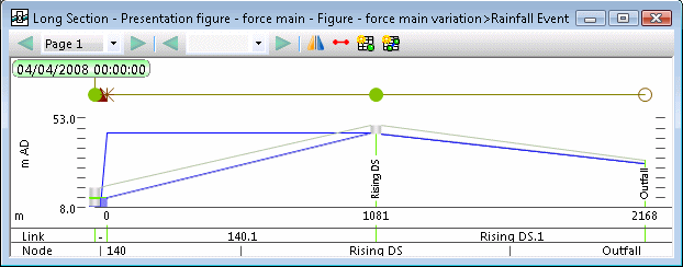
Intermediate points along the forcemain, such as junctions or changes in dimension should be represented using break nodes. These break nodes effectively make the forcemain 'closed' and siphoning will therefore take place as shown in the diagram below.

The diagram above shows that the hydraulic grade line is below pipe invert level for much of the length of the pipes, leading to negative pressures (as would occur in a siphon in reality.) This is represented in graphs and tabular results as negative depth values.

If the downhill sloping conduit is part of the gravity system, it can be simply represented using the "Full" (Conduit Model) solution. However if it is part of the pressurised system please contact the support team for detailed instructions about how to represent it.
The Permeable Solution Model can be used on selected pipes: for example, to model permeable pavements.
The model equation governing permeable media conduits is:
|
|
where: Q - discharge (m3/s) A - pipe full area (m2) n - porosity q - lateral inflow (m2/s) |
Where Discharge is calculated using Darcy's Law:
|
|
where: K - Hydraulic Conductivity A - cross-sectional area of permeable formation Dh/L - hydraulic gradient |

This is a prototype solver therefore results should be verified before being used for engineering purposes.
The Finite Volume solver has been developed to help model complex trans-critical flow scenarios, in particular resolving hydraulic jumps that can occur within a conduit. If a modeller suspects that a conduit undergoes transitions between sub- and super-critical flows, they can select the Finite Volume solution scheme to investigate the changes in modelling output when the trans-critical flow is properly represented. It is not currently possible to see the resolution of a standing wave within the conduit.
The Finite Volume solver is built into the existing solution scheme, whereby it replaces an individual conduit's solution, but still ties-in with the existing node-matrix solver and all existing boundary conditions. The mathematical treatment begins with re-writing the de Saint-Venant equations in conservative vector form for a control volume:
|
|
|
With existing terms defined as above in the Conduit Model (Full solution model), adding P to account for the average pressure of the water volume over the cross-section (depending on depth and geometry shape), and S¦ as the friction slope. The friction slope is defined as:
|
|
|
The flux term F is resolved at the interface between two neighbouring cells, using a Roe Riemann solver. The equations are discretised implicitly in time (from time n to n+1, using the time weighting θ) with a first order spatial discretisation; for a given cell, i:
|
|
|
The implicit terms at time n+1 are linearised with a first-order Taylor series expansion, and re-arranged into a system of linear equations, which are solved analogously to the existing conduit solver.
By default, each conduit is split into N discrete computational points regularly spaced at an interval of 20 times the conduit diameter.
The Preissmann 4-point scheme (Preissmann, 1961) is used to approximate the Saint-Venant equations, in which functions and derivatives are replaced by weighted averages over the four corners of a box in (x,t) space.
|
|
where |
The implicit nature of the scheme removes any restrictions on the timestep,
![]() , by the CFL condition (Courant et al, 1928)
on entering the Preissmann slot and results in a range of unconditional
stability that may be defined in terms of the time weighting parameter,
namely q³ 1/2.
, by the CFL condition (Courant et al, 1928)
on entering the Preissmann slot and results in a range of unconditional
stability that may be defined in terms of the time weighting parameter,
namely q³ 1/2.
In practice, a value of q= 0.65 is used throughout a time-varying simulation, thus introducing a small degree of numerical diffusion (Cunge et al., 1980).
Each pair of adjacent points in a conduit is linked by the discrete form of the Saint-Venant equations, resulting in 2N-2 equations available to describe the flow state. In the case of a control link the two computational points allocated are linked by the prescribed head-discharge relationship.
The local equation system for a link is completed by specifying a boundary condition at each end, of the general form.
|
|
|
relating discharge, Qi, and level, yi. In the case of a conduit this will include the headloss term, and in the case of a free outfall the flow is assumed to be critical.
The equation system is completed by the continuity equation to be satisfied at each internal node:
|
|
|
This is approximated by the implicit Euler Method.
In the case of the Finite Volume solver, the conduit is discretised into N-1 cells, with interfaces in the locations of the standard computational points. This presents a modification to the aforementioned Preissmann weighted 4-point box scheme, with a wider 6-point stencil used.
The discretisation of the governing equations in the conduits, at the conduit boundaries, at the control structures and in the nodes results in a large system of algebraic non-linear finite difference equations to be solved simultaneously at each time level.
The stability of the calculations, particularly in the transition between pressurised and free surface flow, is ensured using the iterative Newton-Raphson method. In the Newton-Raphson Method this system for the dependant variables at the new time level must be linearised, resulting in a large matrix system. A double-sweep method is employed (see Liggett and Cunge, 1975 and Richens, 1985) to reduce the matrix by local elimination of computational nodes along the links between nodes.
The Newton-Raphson Method is characterised by the possibility of potentially quadratic convergence, for instance within three iterations; however, the interactive behaviour of highly looped networks may render this only linear.
Non-linear effects such as steep fronts or wave interaction may result in the timestep being automatically adjusted by progressive halvings until convergence of the Newton-Raphson method is reached. Conversely, rapid convergence may result in the timestep being doubled.
A relative convergence check is employed such that the change in every dependant variable at the new time level is less than 1%.
In a conduit of slope greater than the critical slope there is a likelihood of supercritical conditions. Conversely, in a conduit of slope less than critical, physically the Froude number decreases with depth because the resistance terms in the momentum equation dominate the inertial terms and the flow remains subcritical.
|
|
|
However, a model timestep too large may result in artificial, local supercritical conditions.
Ideally, the modelling of mixed unsteady supercritical and subcritical flows requires an algorithmic structure that remains invariant during the computation; notably the retention of one-point boundary conditions throughout. This is attained by a gradual phasing out of the inertial terms as the Froude number approaches unity so as to maintain subcritical-like characteristic structures everywhere.
The potential difficulty may be avoided prior to simulation by calculating a characteristic Froude number, Fc, for each conduit. The inertial terms are phased out if 0.8 < Fc < 1.0 and removed for Fc>= 1.0. The likelihood of such action is increased in relatively steep conduits. Note this is not applied to the Finite Volume solver, which naturally resolves trans-critical flows.
The resulting equation system may thus be solved by the double-sweep algorithm universally (see Liggett and Cunge, 1975).
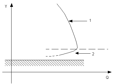
At low depths in a conduit the same discharge may occur at two different downstream depths, as shown in the diagram below. The numerical solution may thus oscillate between the two flow states (Cunge et al., 1980).

The relationship between discharge and downstream depth is as follows:
- Increasing slope dominates.
- Decreasing cross-section dominates.
The instability may be systematically avoided by modification of the finite difference representation of the conveyance term in the momentum equation above. The average of upstream and downstream conditions is replaced by a simple upstream weighting.
This procedure will guarantee stability in the case of a conduit in which inertial terms are not present but the retention of any proportion may still present difficulties. The problem may be circumvented by the addition of a nominal base flow defined as the normal flow at a prescribed base depth in a conduit. The base depth is itself defined as 5% of the conduit height and results in, for example, a base flow of 1.9% of pipe full capacity for circular pipes and 5% for rectangular pipes. The base flow is, however, introduced artificially within the network solver and removed within the boundary conditions. Thus it does not affect volume conservation.


 denotes
  .
.

