Cross Section Window
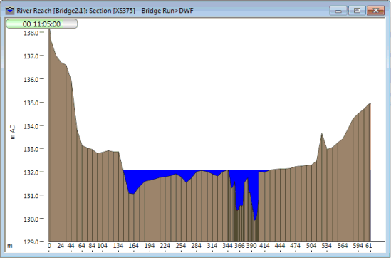
The Cross Section Window displays a cross-section view of a selected section in an InfoWorks network. Using this view you can view simulation results for the selected section. The section can be one of the following objects:
- section in a river reach link
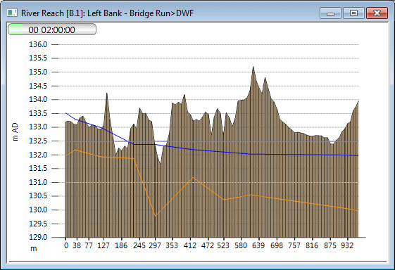
- bank in a river reach link
- section in a bridge link
- inline bank
- results section
The Cross Section Window is modeless and updates as the simulation is replayed.
The Cross Section Window is displayed when the Section pick  button on the More GeoPlan Tools Toolbar is clicked and a section subsequently selected on the GeoPlan.
When displaying a cross section for a river reach bank, traces are displayed representing water levels and ground levels inside and outside of the reach.
The inside level traces represent water and ground levels inside the river reach. The traces are drawn by plotting the levels for the sections defined as bank section markers. Ground levels are plotted as the lowest ground level at each section marker.
The outside level traces represent water and ground levels in a connected structure on the other side of the river reach bank. The connected structure may be a storage node, 2D zone or another river reach. (See River Reach Building Tools for further information on building bank connections.)
If a breach has been modelled along the river reach bank, a trace of time varying bank level is also displayed. The trace represents the bank level as it changes over time based on the RTC definitions used to control movement of the bank points when modelling a breach. The varying bank level trace may not match the fixed bank level trace exactly, as levels are adjusted during simulation to ensure that points are not set below the elevation of objects that the bank abuts. See Breaches in Banks and Linear Structures for details.
 Tip
Tip There is another Section Window in InfoWorks ICM, the Flooding Section Window, which is used to display flooding results on a user-defined section.
Right-click over the cross section to display a context menu with the following options.
Please note that these commands can also be selected from the Section menu when a Cross Section Window is the currently active view.
|
Flip View |
Flip the cross section horizontally, which reverses the direction in which the cross section is being viewed. |
|
Export to AutoCAD DWG |
Save the current long section window to DWG format. The cross section can then be opened and viewed in Autocad. |
|
Move Downstream |
Available when the section being viewed is a river reach cross section. Selecting this option or pressing the SHIFT + PaGe UP keys shows the cross section view for the section downstream of currently displayed section. |
|
Move Upstream |
Available when the section being viewed is a river reach cross section. Selecting this option or pressing the SHIFT + Page down keys shows the cross section view for the section upstream of currently displayed section. |
|
Properties |
Clicking on this button displays the Section Properties dialog, where changes can be made to the way in which the cross section is displayed. |
The following icons on the toolbar allow you to move around the Cross Section view:
|
Zoom In |
Click on the |
|
Zoom Out |
Click on the |
Alternatively, the mouse scroll wheel can be used to zoom in and out on the Cross Section Window.


 button or press
  button, and then click on the Cross Section
view to zoom out from the current view.