River Reach - Bank Flows
Each river bank may be connected to a single object of type River Reach, Storage Area or 2D Zone into which flow from the river reach can spill.
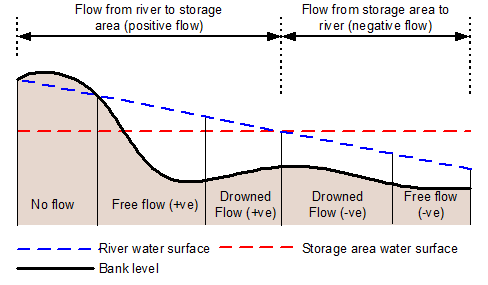
Flow over the bank is calculated as a flow over a jagged or irregular weir. The flow over the bank is calculated by splitting the calculation into determining flows over segments using an integrated form of the weir equation for dry, free and drowned, forward and reverse modes. These flow and associated matrix coefficients are then summed together subject to stability constraints, to give values over the entire bank.
Further discussion of this method can be found in Evans E.P. and von Lany P.H. (1983).
The geometry of the bank, discharge coefficient Cd and modular limit are defined in the river bank section editor accessed via the river reach property sheet.
The levels used to determine spill flow come from the river reach section points, mesh element points along the bank and from any computational nodes (inserted according to the space step settings in the simulation parameters).

Bank flow conditions (see equations below)

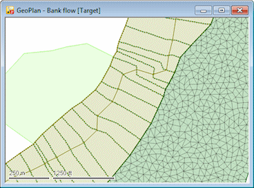
River reach connected to a 2D zone and storage area
Equations
Mode 0 - Zero Flow
|
Condition |
The upstream (highest) water level is below the bank level defined in the spill, or the water levels are above the bank level but almost exactly equal. | ||
| Equation |
where: qs = flow over segments |
Mode 1 - Free Flow (positive sense)
|
Condition |
|
||
| Equation |
where: y11 = upstream water depth in river reach y12 = downstream water depth in river reach y21 = upstream water depth in bank connection object y22 = downstream water depth in bank connection object m = modular limit b = length of bank Special CaseWater surface nearly parallel to bank (y12 ≈ y11) qs = Cd b y11√y11 |
Mode 2 - Drowned Flow (Positive Sense)
|
Condition |
|
||||
| Equation |
where: D = y12 dy21 - y11 dy11 A = Cd / yk2 √(1-m) yk = y12 - y11 - y22 +y21 yi = y12 - y11 dy21 = (y12 - y22) 3/2 dy22 = (y12 - y22) 5/2 dy11 = (y11 - y21) 3/2 dy12 = (y11 - y21) 5/2
Special CasesThe following special cases may occur:
qs = -½ A b yk2 (y11 + y12)√(y11- y21) qs = - 2 A b yk5/2 {y11/3 + (y12 - y11)/5} qs = -½ A yk2 (2y11 + yi + yk y11/ym)√(y11- y21) where: yk= y12 - y11- y22 + y21 ym= y12 - y21 yi= y12 - y11
Note: The derivatives for the drowned weir equation approach infinity as the head difference over the bank approaches zero. This may result in the solution oscillating around zero head difference. In order to avoid oscillating flows as the head difference over the bank approaches zero, linearised flow equations will be used when the head difference at both ends of a segment is below the Drowned bank linearisation threshold specified in the Simulation Parameters (0.01m default).
where: y1 = upstream depth y2 = downstream depth dhlin = linearised head threshold |
Mode 3 - Free flow (Negative Sense)
The same formulae apply as for mode 1 but with y21 interchanged with y11, and y12 interchanged with y22.
Mode 4 - Drowned flow - (Negative Sense)
The same formulae apply as for mode 2 but with y21 interchanged with y11, and y12 interchanged with y22.
Derivation of Discharge Coefficient Cd
The discharge coefficent Cd includes discharge, velocity and calibration coefficients, specified in SI units.
The basic weir equation used for free flow over the bank is:
|
Typical Cd values are 1.85 for sharp crested weirs and 1.7 for round nosed horizontal-crested weir. The Cd value should be reduced where the 'weir' feature is less efficient than man-made concrete weirs, for example for flood embankments. Accurate guidance on the selection of Cd values for maintained grass embankments is not available although current good practise suggests values in the range 1.7 to 1.0. To model flow over natural ground which is less efficient than a flood bank, values lower than 1.0 may be applicable. These lower values may include an allowance for friction losses for overland flow (see below for an equation which may aid determination of coefficients under such circumstances).
When modelling floodplain flow, it is possible, by analogy with the equation for fully rough flow, to derive an approximate formula for the discharge coefficient. The formula requires the average depth of flow, an estimate of Manning's n and the distance between the spill source and sink:®
where: d = average depth of flow (m) DX = distance between spill source and sink (m) n = Manning's n for region of flow (e.g. 0.1) m = user defined modular limit (e.g. 0.8) |
This formula has the necessary properties that the level difference increases for larger values of n and DX whilst it decreases for larger values of d. Ideally Cd should be a function of flow depth, however as it is fixed, users should use a single representative value of d thus giving a constant Cd for the run duration. It is also worth noting that the formula applies for drowned flows, for which the assumption of fully friction dominated flow is valid.


