After setting up our first scenario with a pump control, we can now create a new scenario to perform more complex tasks. This is achieved by adding further ranges and rules as dependents for the regulator. You can also add more regulators to control other parts of the network.
In this stage, the existing scenario will be duplicated to create a new scenario to model a breakdown in the pump between 6 A.M. and 7 A.M.

This stage assumes that you have started InfoWorks ICM and that Master database, containing the ICM Basic Tutorial, is opened in the Explorer window, showing the 'Langley Catchment Study' model group.
To create a new RTC scenario:
- Open the 'Langley RTC (TUT)' network if not already open.

- Select the Scenarios | Manage scenarios option from the Network menu.
The Manage Scenarios dialog is displayed.
- Click the Create... button and the Create New Scenario dialog is displayed.
- Name the new scenario 'Pump Control 2'
- Check the Copy an existing scenario box
- Select 'Pump Control' from the Scenario to copy drop-down list.
- Click OK.
-
In the Manage Scenarios dialog, select the 'Pump Control 2' scenario and click the Select button. The dialog closes and the new scenario is now active in the GeoPlan.
- Set up the controls for the new 'Pump Control 2' scenario:
- Ensure that the 'Langley RTC (TUT)' network is still open on the GeoPlan and that the active scenario is the 'Pump Control 2'.
- Open the RTC Editor.
The RTC Editor is displayed.
- Click the
 (Expand) button to the left of the pump regulator entry to display its dependents and adjust the column widths, if necessary.
 -
Add a global range (which can be used by any regulator):
- Right-click the 'Global item' and select Insert dependent | Range from the pop-up menu.
- Enter a Name of 'TimeOff' and select the 'TR - time repeat' option from the Type drop-down list.
- Enter '06:00:00' as the Minimum and '07:00:00' as the Maximum Time/Date. In each case, select 'Daily' from the drop-down list.
- Click the Update button.
- Add the new rule for the regulator:
- Right-click the pump item and select Insert dependent | Rule from the pop-up menu.
- For the Condition, select 'TimeOff' from the drop-down list.
- For the Type,
select 'OFF' from the drop-down list.
- Click the Update button.
- Inspect the scenario:
- Click any item in the list to view or edit its definition.
- Click the regulator to specify whether the rules override any controls in the network and to give it an initial value. The full description of the regulator is shown in the box at the bottom of the right-hand pane.
- Save the changes:
- Click the
 (Close) button to save the pump regulator definition and close the RTC Editor window.
 - Validate the network and its associated scenario.
- Commit the changes to the network.
- Run the simulation with the revised scenario:
- Open the 'Regulate Pump' run.
The Schedule Hydraulic Run dialog is displayed.
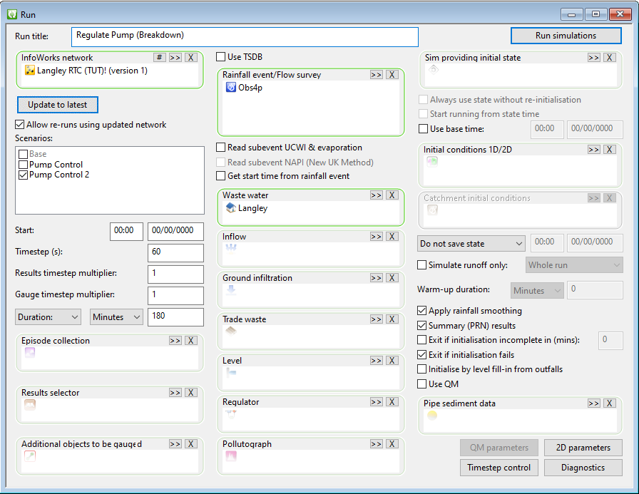
- In the Run title field, change the title to 'Regulate Pump (Breakdown)'.
- Click the Update to Latest button.
- Check the Allow re-runs using updated network box.
- Check the box next to the Pump Control 2 option in the Scenarios field.
The settings for all other options remain unchanged.
- Click the Run simulations button.
A Schedule Job(s) dialog is displayed.
- Click the OK button.
InfoWorks ICM processes the run and its progress can be viewed in the Job Control window.
- View the simulation results:
- Open the simulation from the 'Regulate Pump
(Breakdown)' run.
The results are opened in the GeoPlan.
- Use the
 (Graph pick) button to display
graphs of Level for 44636499 and Pump State for 44636499.1.
(Graph pick) button to display
graphs of Level for 44636499 and Pump State for 44636499.1. - Zoom in on the pump region. You can, for example, use the Find in GeoPlan option in the GeoPlan menu or click the
 (Find in GeoPlan) tool, to zoom onto the manhole that contains the pump. In the dialog, enter the node id, in this case, 44636499, and click the Find button, and the GeoPlan will be centred on the specified manhole.
 - Use the button to display
graphs of Level for '44636499' and Pump State for '44636499.1'.
- Arrange the views horizontally.
- Close the GeoPlan and graph views. Click the (Close) button in the top right of the windows.

The Create New Scenario dialog closes and the new scenario is added to the list of scenarios in the Manage Scenarios dialog.

The entry on the left is updated with the new details.


The next stage looks at further ways of editing a scenario.
 Back to flowchart
